SKR 5302: Advanced Distributed Computing
| Site: | PUTRA-eX |
| Course: | AI |
| Book: | SKR 5302: Advanced Distributed Computing |
| Printed by: | Guest user |
| Date: | Wednesday, 17 June 2026, 8:52 AM |
Description
SKR 5302: Advanced Distributed Computing © 2025 by Masnida Hussin is licensed under CC BY-SA 4.0![]()
![]()
![]()
Table of contents
- 1. Chapter 1: A Review : Distributed System
- 1.1. What is a Distributed System?
- 1.2. Characteristics of Distributed System
- 1.3. Examples of Distributed Systems
- 1.4. Advantages and Disadvantages of Distributed Systems
- 1.5. Design Issues in Distributed Systems
- 1.6. Resource Sharing and The Web
- 1.7. Example of the Web
- 1.8. Challenges
- 1.9. Summary Chapter 1
- 2. System Model: Distributed System
- 3. Chapter 3: Networking and Internetworking
- 4. Chapter 4: Inter-process Communication
- 4.1. Introduction
- 4.2. Internet Applications Serving Local and Remote Users
- 4.3. The Internet protocol
- 4.4. IP as a basis for a communication channel
- 4.5. The characteristics of inter-process communication
- 4.6. Elements of C-S Computing
- 4.7. Network Layering
- 4.8. Sockets
- 4.9. Connection-oriented & Connectionless Datagram Socket
- 4.10. UDP datagram communication
- 4.11. External data representation and marshaling introduction
- 4.12. CORBA’s Common Data Representation (CDR)
- 4.13. Java object serialization
- 5. Chapter 5: Distributed Operating System
- 6. Chapter 6: Coordination and Agreement
- 7. Chapter 7: Transaction and Concurrency Control
- 8. Chapter 8: Replication
- 9. Chapter 9: Peer-to-peer networks
- 9.1. Introduction
- 9.2. Routing Overlays
- 9.3. Application architectures
- 9.4. Pure P2P architecture
- 9.5. P2P: searching for information
- 9.6. Peer-to-Peer Networks: Gnutella
- 9.7. Hierarchical Overlay
- 9.8. P2P Case study: Skype
- 9.9. Peer-to-Peer Networks: KaAzA
- 9.10. Peer-to-Peer Networks: BitTorrent
- 9.11. Overlay Networks
- 9.12. Distributed Hash Tables
- 9.13. Applications of DHTs
- 9.14. Conclusions
1. Chapter 1: A Review : Distributed System
Overview:
1.1. What is a Distributed System?
- A
distributed system is a collection of autonomous computers
linked by a computer network that appear to the users of the system as a single
computer.
- From
a system architecture perspective: The
machines are autonomous; this means they are computers which in principle,
could work independently
- From
the user’s perception: the distributed system is perceived as a single system
solving a certain problem (even though, in reality, we have several computers
placed in different locations).
By
running a distributed system software the computers are enabled to:
- coordinate their activities
- A distributed system is a collection of autonomous computers linked by a computer network that appear to the users of the system as a single computer.
-
- share resources: hardware, software, data.
Hence, Internet as such, is not a distributed system, but an infrastructure on which to implement distributed applications/services (such as the World Wide Web).
1.2. Characteristics of Distributed System
- Concurrencyconcurrent programs execution – share resource
- No global clockprograms coordinate actions by exchanging messages
- Independent failures
when some systems fail, others may not know
Share resources
- It characterizes the range of the things that can usefully be shared in a networked computer.
- It extends from hardware components to software-defined entities.
- It includes the stream of video frames and the audio connection.
1.3. Examples of Distributed Systems
- Network of workstations
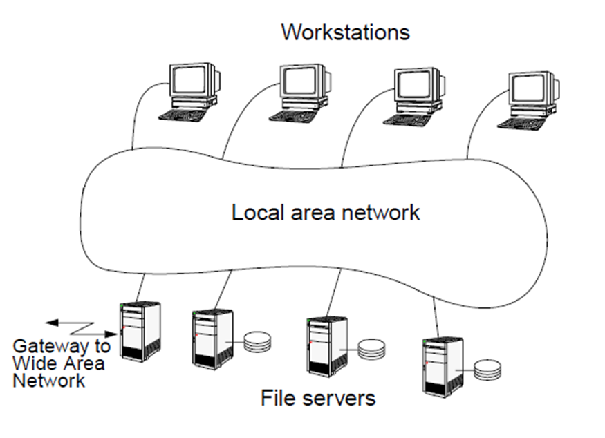
- Personal workstations and processors not assigned to specific users.
- Single file system, with all files accessible from all machines in the same way and using the same path name.
- For a certain command the system can look for the best place (workstation) to execute it.
- Automatic banking (teller machine) system
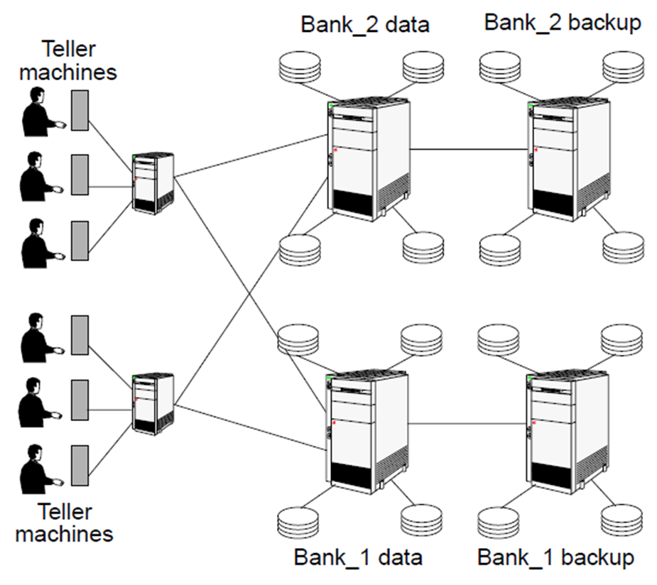
- Primary requirements: security and reliability.
- Consistency of replicated data.
- Concurrent transactions (operations which involve accounts in different banks; simultaneous access from several users, etc).
- Fault tolerance
- Automotive system (a distributed real-time system)
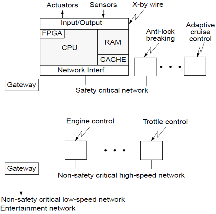
- Synchronization of physical clocks
- Scheduling with hard time constraints
- Real-time communication
- Fault tolerance
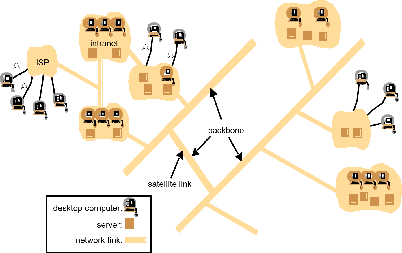
Internet
- It is a very large distributed system that allows users throughout the world to make use of its services.
- Internet protocols is a major technical achievement.
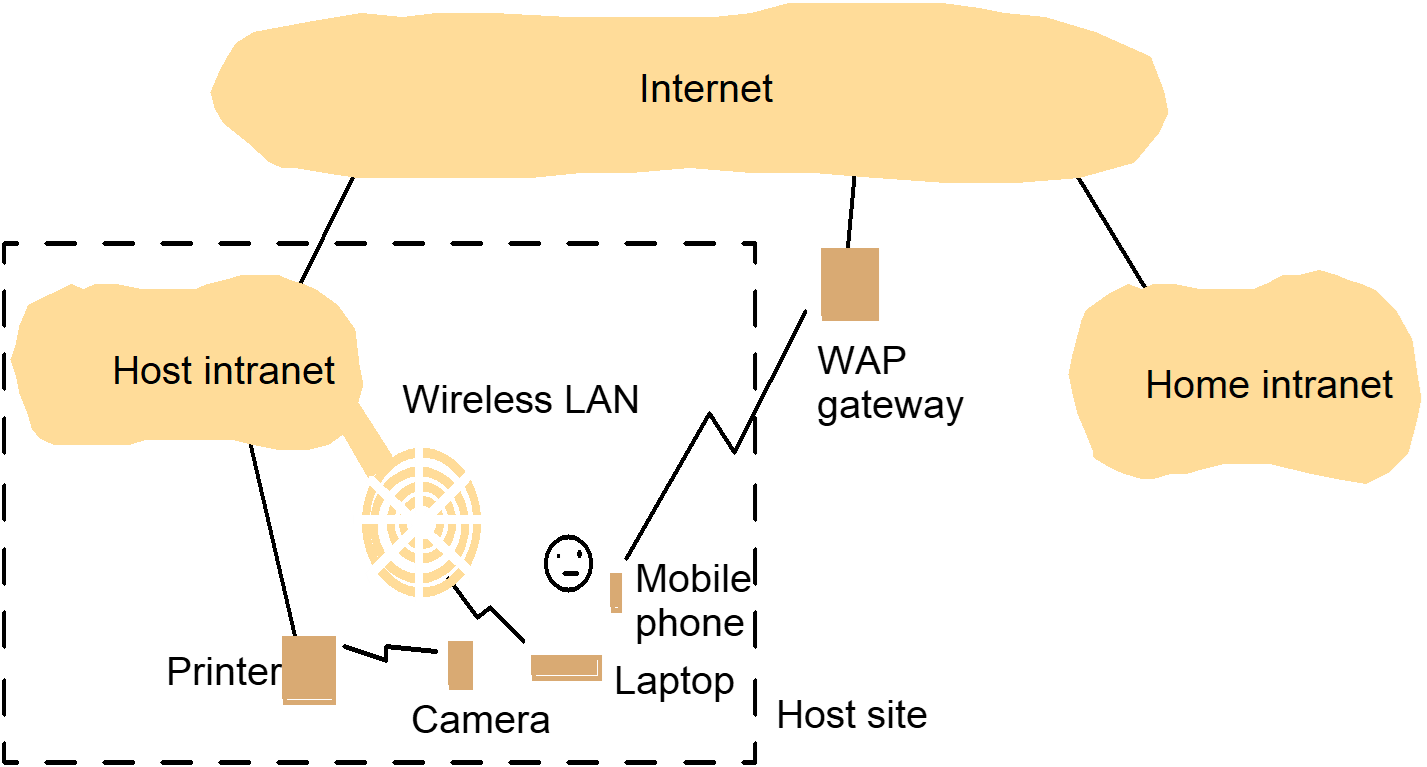
Mobile computing (nomadic computing)
- Access resources while on the move or in an unusual environment
- Location-aware computing: utilize resources that are conveniently nearby
Ubiquitous computing (pervasive computing)
- The harnessing of many small, cheap computational devices
- Laptop computers
- Handheld devices
- PDA, mobile phone, pager, video camera, digital camera
- PDA, mobile phone, pager, video camera, digital camera
- Wearable devices
- e.g. smart watches, digital glasses
- Network appliances
- e.g. washing machines, hi-fi systems, cars and refrigerators
- e.g. washing machines, hi-fi systems, cars and refrigerators
Portable and handheld devices in a distributed system |
|---|
 |
1.4. Advantages and Disadvantages of Distributed Systems
Advantages of Distributed Systems
- Performance:
Very often a collection of processors can provide higher performance (and better price/performance ratio) than a centralized computer. - Distribution:
Many applications involve, by their nature, spatially separated machines (banking, commercial, automotive system). - Reliability (fault tolerance):
If some of the machines crash, the system can survive. - Incremental growth:
As requirements on processing power grow, new machines can be added incrementally. - Sharing of data/resources:
Shared data is essential to many applications banking, computer supported cooperative work, reservation systems); other resources can be also shared (e.g. expensive printers). - Communication:
Facilitates human-to-human communication.
- Difficulties of developing distributed software:
how should operating systems, programming languages and applications look like? - Networking problems:
several problems are created by the network infrastructure, which have to be dealt with: loss of messages, overloading, ... - Security problems:
sharing generates the problem of data security.
1.5. Design Issues in Distributed Systems
Design Issues in Distributed Systems
- Transparency
- Communication
- Performance & scalability
- Heterogeneity
- Openness
- Reliability & fault tolerance
- Security
- Transparency
- Communication
- Performance & scalability
- Heterogeneity
- Openness
- Reliability & fault tolerance
- Security
1.6. Resource Sharing and The Web
Resource sharing
- Is the primary motivation of distributed computing
- Resources types
- Hardware, e.g. printer, scanner, camera
- Data, e.g. file, database, web page
- More specific functionality, e.g. search engine, file
Service
- manage a collection of related resources and present their functionalities to users and applications
- a process on networked computer that accepts requests from processes on other computers to perform a service and responds appropriately
- the requesting process
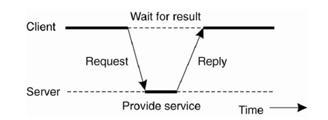
Remote invocation
- A complete interaction between client and server, from the point when the client sends its request to when it receives the server’s response
Motivation of WWW
- Documents sharing between physicists of CERN
Web is an open system: it can be extended and implemented in new ways without disturbing its existing functionality.
- Its operation is based on communication standards and document standards
- Respect to the types of ‘resource’ that can be published and shared on it.
1.7. Example of the Web
- HyperText Markup Language
A language for specifying the contents and layout of pages
- Uniform Resource Locators
Identify documents and other resources
- A client-server architecture with HTTP
By with browsers and other clients fetch documents and other resources from web servers
Example of the Web : html
<IMG SRC = http://www.cdk3.net/WebExample/Images/earth.jpg> <P> Welcome to Earth! Visitors may also be interested in taking a look at the <A HREF = “http://www.cdk3.net/WebExample/moon.html">Moon</A>. <P> (etcetera) |
|---|
- HTML text is stored in a file of a web server.
- A browser retrieves the contents of this file from a web server.
- To identify which web server maintains the resource
- To identify which of the resources at that server
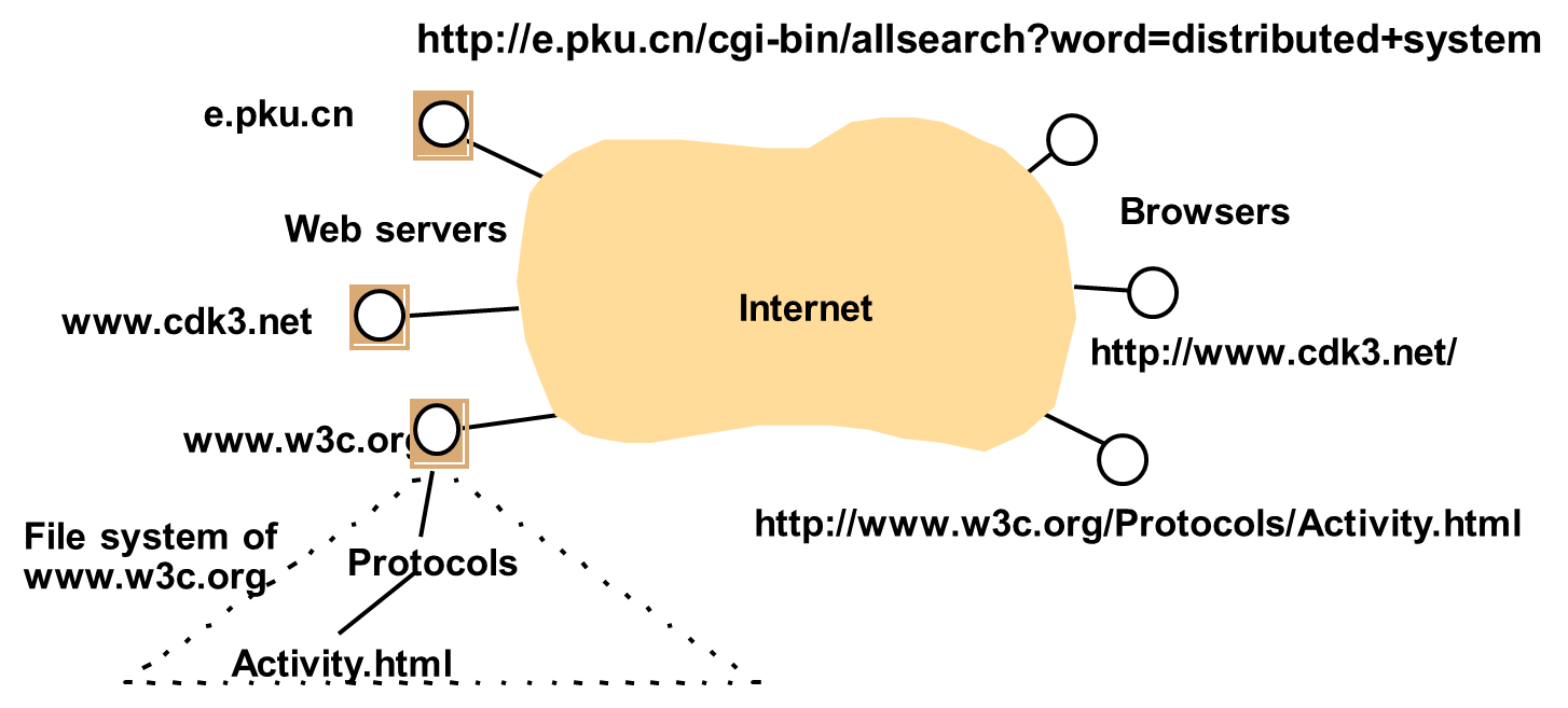
Example of the Web : URL
- Scheme: scheme-specific-location
| mailto:joe@anISP.net |
| http://net.pku.cn/ |
|---|
- HTTP URLs are the most widely used
- An HTTP URL has two main jobs to do:
- To identify which web server maintains the resource
- To identify which of the resources at that server
- http://servername[:port]//pathNameOnServer][?arguments]
- e.g.

| Server DNS name | Pathname on server | Arguments |
|---|---|---|
| www.cdk3.net | (default) | (none) |
| www.w3c.org | Protocols/Activity.html | (none) |
| e.pku.cn | cgi-bin/allsearch | word=distributed+system |
- Publish a resource remains unwieldy
Example of the
Web : HTTP
- Defines the ways in which browsers and any other types of client interact with web servers (RFC2616)
- Main features
- Request-replay interaction
- Content types. The strings that denote the type of content are called MIME (RFC2045,2046)
- One resource per request. HTTP version 1.0
- Simple access control
- Dynamic content
- Common Gateway Interface: a program that web servers run to generate content for their clients
- Common Gateway Interface: a program that web servers run to generate content for their clients
- Student : Downloaded code JavaScript or Applet that shows web functions and services.
Discussion of Web
- Dangling: a resource is deleted or moved, but links to it may still remain
- Find information easily: e.g. Resource Description Framework which standardize the format of metadata about web resources
- Exchange information easily: e.g. XML – a self describing language
- Scalability: heavy load on popular web servers
- More applets or many images in pages increase in the download time
1.8. Challenges
Heterogeneity
- Networks
- Ethernet, token ring, etc
- Computer
hardware
- big endian / little endian
- Operating
systems
- different API of Unix and Windows
- Programming
languages
- different representations for data structures
- Implementations
from different developers
- no application standards
- Middleware
- applies to a software layer that provides a programming abstraction as well as masking the heterogeneity of the underlying networks, hardware, OSs and programming languages
- Mobile
code
- is used to refer to code that can be sent from one computer to another and run at the destination
Openness
- Openness
of a computer system
- is the characteristic that determines whether the system can be extended and re-implemented in various way. e.g. Unix
- Openness of distributed systems
- is determined by the degree to witch new resource sharing services can be added and be made available for use by A variety of client programs. e.g. Web
- How to deal with openness?
- key interfaces are published, e.g. RFC
Security
- Confidentiality
- protection against disclosure to unauthorized individuals, e.g. ACL in Unix File System
- Integrity
- protection against alteration or corruption, e.g. checksum
- Availability
- protection against interference with the means to access the resources, e.g. Denial of service
Scalability
- A system is described as scalable
- if will remain effective when there is a significant increase in the number of resources and the number of users
- A scalable example system: the Internet
- design challenges
- The cost of physical resources, e.g., servers support users at most O(n)
- The performance loss, e.g., DNS no worse than O(logn)
- Prevent software resources running out, e.g., IP address
- Avoid performance bottlenecks, e.g., partitioning name table of DNS, cache and replication
| Date | Computers | Web servers | Percentage |
|---|---|---|---|
1993, July | 1,776,000 | 130 | 0.008 |
1995, July | 6,642,000 | 23,500 | 0.4 |
1997, July | 19,540,000 | 1,203,096 | 6 |
1999, July | 56,218,000 | 6,598,697 | 12 |
Failure Handling
- Detecting
- e.g. checksum for corrupted data
- Sometimes impossible so suspect, e.g. a remote crashed server in the Internet
- Masking
- e.g. Retransmit message, standby server
- Tolerating
- e.g. a web browser cannot contact a web server
- Recovery
- e.g. Roll back
- Redundancy
- e.g. IP route, replicated name table of DNS
- Correctness
- ensure the operations on shared resource correct in a concurrent environment
e.g. records bids for an auction
- ensure the operations on shared resource correct in a concurrent environment
- Performance
- Ensure the high performance of concurrent operations
Transparency
- Access transparency
- using identical operations to access local and remote resources, e.g. a graphical user interface with folders
- Location transparency
- resources to be accessed without knowledge of their location, e.g. URL
- Concurrency transparency
- several processed operate concurrently using shared resources without interference with between them
- Replication transparency
- multiple instances of resources to be used to increase reliability and performance without knowledge of the replicas by users or application programmers,
e.g. realcourse(http://vod.yf.pku.edu.cn/) - Failure transparency
- users and applications to complete their tasks despite the failure of hardware and software components, e.g., email
- Mobility transparency
- movement of resources and clients within a system without affecting the operation of users and programs, e.g., mobile phone
- Performance transparency
- allows the system to be reconfigured to improve performance as loads vary
- Scaling transparency
- allows the system and applications to expand in scale without change to the system structure or the application algorithms
1.9. Summary Chapter 1
- Distributed systems are pervasive
- Resource sharing is the primary motivation for constructing distributed systems
- Characterization of Distributed System
- Concurrency
- No global clock
- Independent failures
- Challenges to construct distributed system
- Heterogeneity
- Openness
- Security
- Scalability
- Failure handling
- Concurrency
- Transparency
2. System Model: Distributed System
Overview
- What is a system model?
- Types of system model
- Description of physical model
- Description of architecture model
- Description of fundamental model
- Description of security model
2.1. Overview
- What is a system model?
- Types of system model
- Description of physical model
- Description of architecture model
- Description of fundamental model
- Description of security model
2.2. What is a system model?
|
|---|
2.3. Types of system model
Three types of models
|
|---|
2.4. Physical model
| Distributed Systems | Early | Internet-scale | Contemporary |
|---|---|---|---|
|
Scale |
Small | Large | Ultra-large |
| Heterogeneity |
Limited (typically relatively |
Significant in terms of platforms,
|
Added
dimensions introduced including radically different styles of architecture |
| Openness |
Not a priority |
Significant priority with range of standards introduced |
Major research challenge with existing standards not yet able to embrace complex systems |
|
Quality of Service |
Not a priority |
Significant priority with range of services introduced |
Major research challenge with existing standards not yet able to embrace complex systems |
2.5. Architecture Model
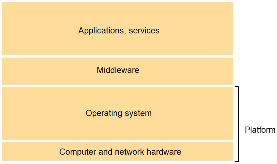
Layered architecture
Software and hardware service layers in distributed systems
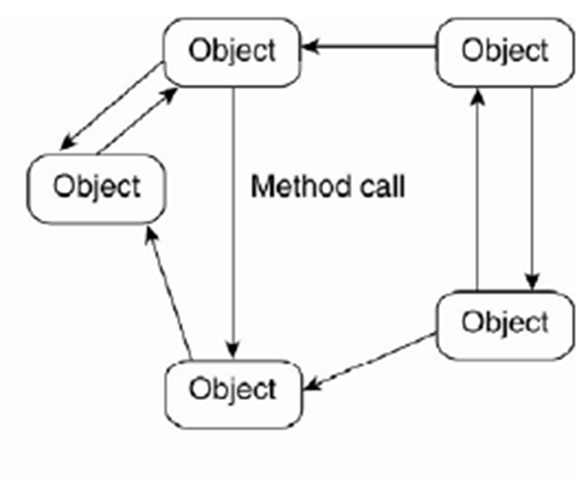
Layered architecture (example) 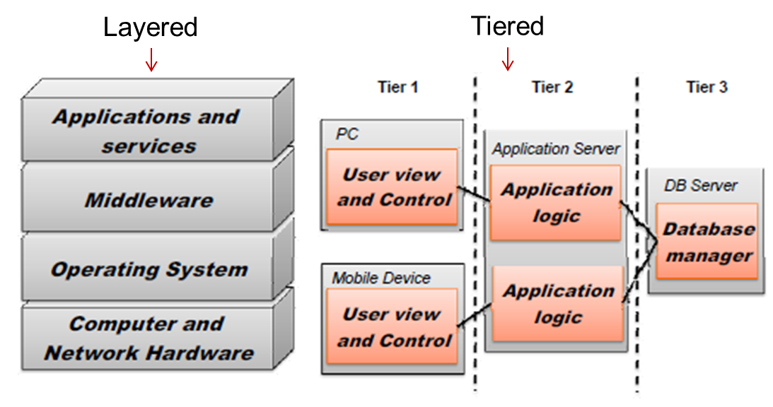 Object-based architecture
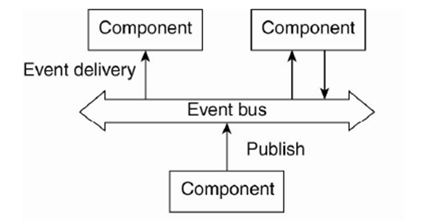
Event-based architecture
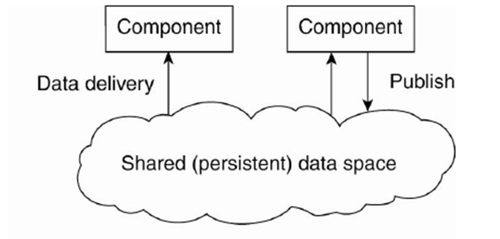
Data-centered architecture
Decentralized-system architecture
Performance Issues
SKR5302 Focuses
|
|---|
2.6. Fundamental Model
Fundamental Model :
|
|---|
2.7. Failure Model
Specification of Failure Model
Omission Failure
Arbitrary Failure (Byzantine failure)
|
|---|
2.8. Security Model
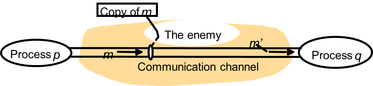
The Enemies
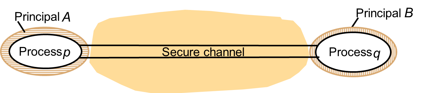
Secure Channel
|
|---|
2.9. Summary
Three types of system models
|
|---|
3. Chapter 3: Networking and Internetworking
OVERVIEW
- Networking
issues for distributed systems
- Types
of network
- Network
performance
- Packet
Transmission
- Data
Streaming
- Switching
Schemes
- Protocols
3.1. Networking issues for distributed systems
- Performance
- Latency
- Delay that occurs after a send operation is executed and before data starts to arrive at the destination computer
- Determined by software overheads, routing delays, etc.
- Data transfer rate
- Speed at which data can be transferred between two computers in the network once transmission has begun, usually quoted in bits per second.
- Determined by its physical characteristics
- Latency
- The time required for a network to transfer a message containing length bits between two computers:
- Message transmission time = latency + length / data transfer rate
- Latency is often of equal or greater significance than transfer rate in determining the performance
- Many messages transferred are small in size
- Total system bandwidth
- Total volume of traffic that can be transferred across the network in a given time.
- The time required to access shared resources on a local network remains a thousand times greater than that required to access resources in local memory.
- Networks often outperform hard disks; local web server or file server with a large-in-memory cache can match or outstrip access to files stored on a local hard disk.
- Scalability
- Future traffic is expected to grow at least in proportion to the number of active users.
- For Internet, some substantial changes to the addressing and routing mechanisms are in progress in order to handle the next phase of the Internet’s growth.
- Reliability
- The reliability of most physical transmission media is very high.
- Errors are usually due to failures in the software at the sender or receiver or buffer overflow
- Security
- Firewall
- To enable distributed applications to move beyond the restrictions imposed by firewalls.
- There is a need to produce a secure networking environment in which a wide range of distributed applications can be deployed, with end-to-end authentication, privacy and security.
- Cryptographic techniques
- The need to protect the routers against unauthorized interference
- The need for secure links to mobile devices
- Mobility
- Wireless networks provide connectivity to mobile devices
- But the addressing and routing schemes of the Internet are not well adapted to their need for intermittent connection to many different subnets.
- The Internet’s mechanisms need to be extended to support mobility and further growth in the use of mobile devices will demand further development.
- Quality of service
- Include the ability to meet deadlines when transmitting and processing streams of real-time multimedia data.
- Major new requirements on computer networks
- Required guaranteed bandwidth and bounded latencies.
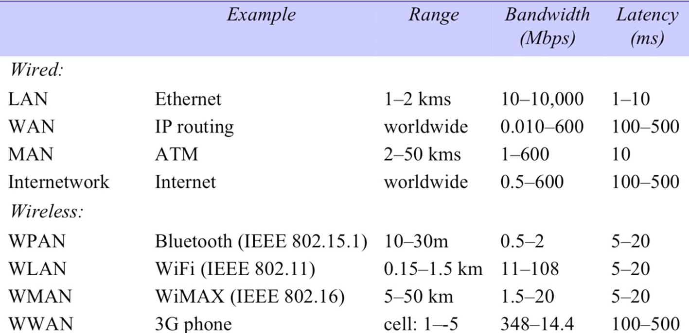
3.2. Types of network
- Personal area networks (PANs)
- Subcategory of local networks
- Various digital devices carried by a user are connected by a low-cost, low-energy network.
- WPANs are of increasing importance due to the number of personal devices such as mobile phones, tablets, digital cameras, music players are now carried by many people
- Local area networks (LANs)
- Carry messages at relatively high speeds between computers by a single communication medium, such as twisted copper wire, coaxial able or optical fibre.
- Segment
- section of cables that serves a department / floor of a building
- No routing of messages is required
- Total system bandwidth is shared
- Total system bandwidth is high and latency is low, except when message traffic is very high.
- Ethernet, token rings and slotted rings
- Wide area networks (WANs)
- Carry messages at lower speeds between nodes that are often in different organizations and maybe separated by large distances.
- Routers
- Route messages or packets to their destinations
- Delay at each point in the route
- Total latency for the transmission depends on the route that it follows and the traffic loads in the various network segments that it traverses.
- Metropolitan area networks (MANs)
- Based on the high bandwidth copper and fibre optic cabling
- Ethernet, ATM
- Wireless local area networks (WLANs)
- For use in place of wired LANs to provide connectivity for mobile devices
- IEEE 802.11 (WiFi)
- Wireless metropolitan area networks (WMANs)
- IEEE 802.16 (WiMAX)
- Aims to provide an alternative to wired connections to home and office buildings
- Wireless wide area networks (WWANs)
- Mobile phone networks are based on digital wireless network technologies such as GSM (Global System for Mobile Communication) standard.
- Operate over wide areas (typically entire countries or continents) through the use of cellular radio connections
- Offer wide area mobile connections to the Internet for portable devices
- Internetworks
- Several networks are linked together to provide common data communication facilities that overlay the technologies the protocols of the individual component networks and the methods used for their interconnection.
- Needed for the development of extensible, open distributed systems.
- Internet
3.3. Network performance
3.4. Packet Transmission
- Messages
- logical unit of transmission in computer networks
- Sequence of data items of arbitrary length
- Message is subdivided into packets.
- Packets
- Sequence of binary data (an array of bits or bytes) of restricted length.
- Contain addressing information to identify the source and destination computers.
- Packets of restricted length are used:
- Each computer in network can allocate sufficient buffer storage to hold the largest possible incoming packet.
- To avoid the undue delays that would occur in waiting for communication channels to become free if long messages were transmitted without subdivision.
3.5. Data Streaming
- Transmission of audio and video in real time.
- Required higher bandwidths and bounded latencies.
- Depends upon the availability of connections with adequate quality of service – bandwidth, latency and reliability
- Ability to established a channel from the source to the destination of a multimedia stream, with a predefined route through the network,
- a reserved set of resources at each node through which it will travel and buffering where appropriate to smooth any irregularities in the flow of data through the channel.
- ATM networks
- provide high bandwidth and low latencies.
- IPv6 has features that enable each of the IP packets in a real-time stream to be identified and treat separately from other data at the network level.
- RSVP (Resource Reservation Protocol)
- Zhang et al. 1993
- Enables applications to negotiate the pre-allocation of bandwidth for real-time data streams.
- RTP (Real Time Transport Protocol)
- Schulzrinne et al. 1996
- Application-level data transfer protocol that includes the details of the play time and other timing requirement in each packet.
3.6. Switching Schemes
- Broadcast
- Involves no switching
- Everything is transmitted to every node, and it’s up to the potential receivers to notice transmissions addressed to them.
- Ethernet
- Wireless networking
- Broadcasts are arranged to reach nodes grouped in cells.
- Circuit switching
- Telephone network
- POTS (plain old telephone system)
- When a caller dialed a number, the pair of wires from the phone to the local exchange was connected by an automatic switch at the exchange to the pair of wires connected to the other party’s phone.
- Telephone network
- Packet switching
- Store-and-forward network
- Each packet arriving at a node is first stored in memory at the node and then processed by a program that transmits it on an outgoing circuit;
- which transfers the packet to another node that is closer to its ultimate destination.
- which transfers the packet to another node that is closer to its ultimate destination.
- Frame relay
- Problems of switching packets in store-and-forward network
- Switching packet through each network node takes anything from a few tens of microseconds to a few milliseconds.
- Switching delay depends on the packet size, hardware speed, etc.
- Even short Internet packets take up to 200 milliseconds to reach their destinations.
- Delay is too long for telephony and video conferencing (delay less than 50 milliseconds)
- Problems of switching packets in store-and-forward network
- Frame relay
- Overcome the delay problems by switching small packets (frames) on the fly.
- Switching nodes
- Routes frames based on the examination of their first few bits
- Not stored at nodes
- ATM network
3.7. Protocols
- General
- Set of rules and formats to be used for communication between processes to perform a given task.
- Two parts:
- A specification of the sequence of messages that must be exchanged
- A specification of the format of the data in the messages
- Implemented by a pair of software modules located in the sending and receiving computers.
- Example:
- A transport protocol transmits messages of any length from a sending process to a receiving process.
- Sending process issues a call to a transport protocol module, passing it a message in the specified format.
- Transport software subdividing the message into packets of some specified size and format that can be transmitted to the destination via the network protocol.
- Corresponding transport protocol module in the receiving computer receives the packet via the network-level protocol module and perform inverse transformations to regenerate the message before passing it to a receiving process.
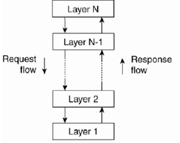
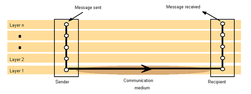
- Protocol layers
- Each layer presents an interface to the layers above it that extends the properties of the underlying communication system.
- A layer is represented by a module in every computer connected to the network.
- Each layer provides a service to the layer above it and extends the service provided by the layer below it.
- Conceptual
layering of protocol software
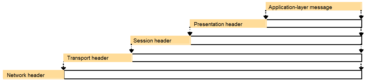
- Encapsulation
as it is applied in layered protocols
- Protocol suites
- Complete set of protocol layers
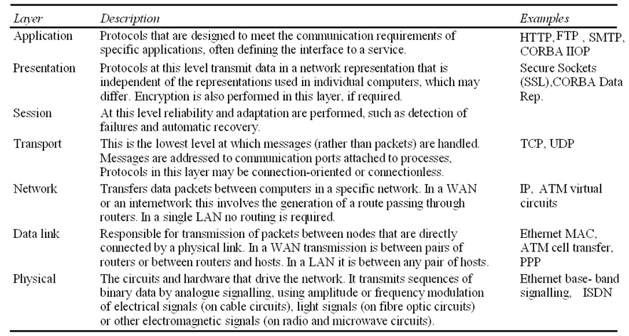
- OSI (Open Systems Interconnection) adopted by ISO (International Organization for Standardization)
- Simplifying and generalizing the software interfaces, but it carries significant performance costs.
- Transmission of application-level message via a protocol stack with N layers involves N transfers of control to the relevant layer, at least one involve operating system entry, and taking N copies of the data as a part of the encapsulation mechanism.
- The implementation of the Internet does not follow the OSI model:
- The application, presentation and session layers are not clearly distinguished in the Internet protocol stack.
- Session layer is integrated with the transport layer.
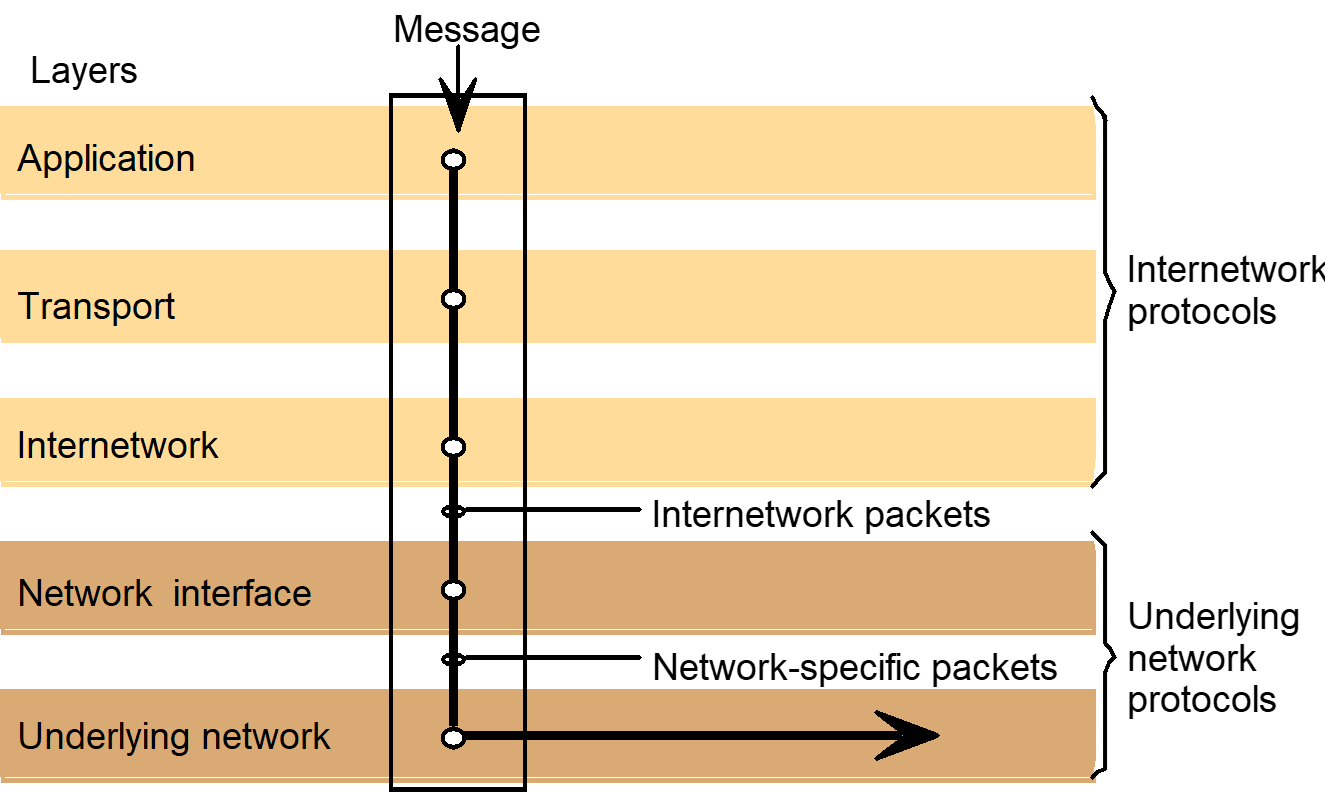
- Internetwork protocol suites include an application layer, a transport layer and an internetwork layer.
- Internetwork layer is a virtual network layer that transmit internetwork packets to destination computer.
- Network interface layer accepts internetwork packets and converts them into packets suitable for transmission by the network layers of each underlying network.
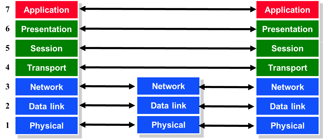
- Protocol
layers in the ISO Open Systems Interconnection (OSI) model
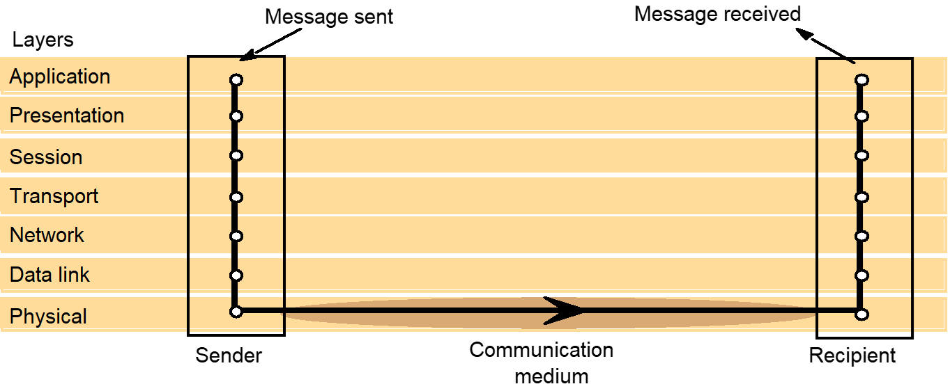
- OSI
protocol summary
Internetwork layers
- Packet assembly
- Transport layer
- Dividing messages into packets before transmission and reassembling them at the receiving computer
- Network-layer protocol packets consists of a header and data field.
- Data field is variable in length, with the maximum length called the maximum transfer unit (MTU).
- If the length of a message exceeds the MTU, it must be fragmented into chunks with sequence numbers and transmitted in multiple packets.
- Example: MTU for Ethernets is 1500 bytes.
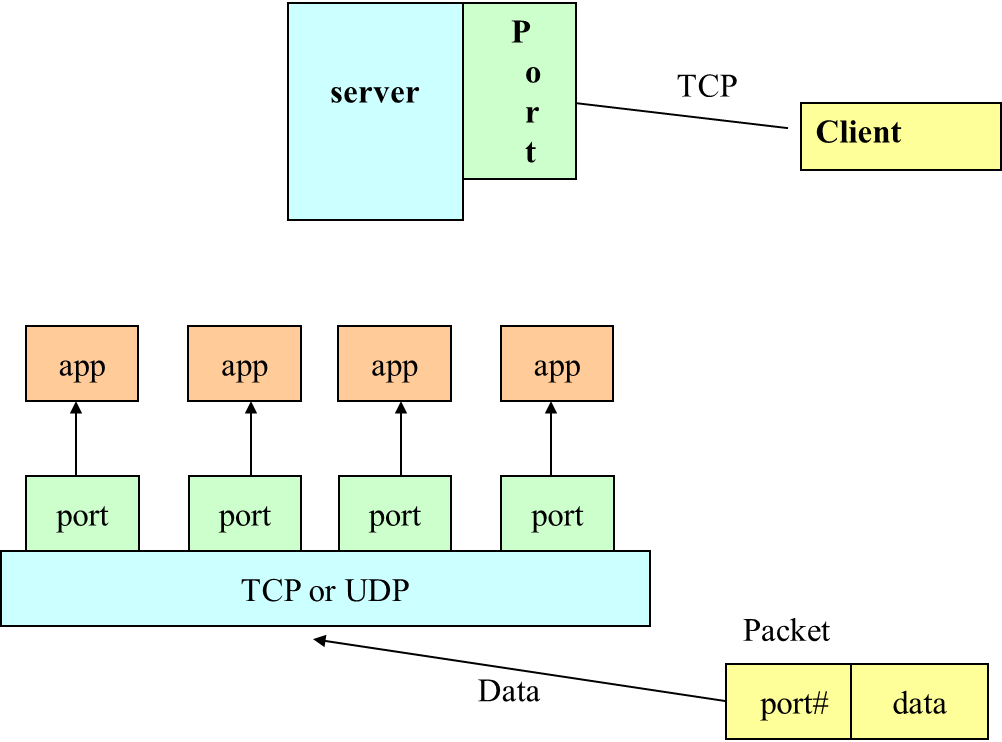
- Ports
- Software-defined destination points at a host computer.
- Attached to processes, enabling data transmission to be addressed to a specific process at a destination node.
- Addressing
- The transport layer is responsible for delivering messages to destinations with transport addresses that are composed of the network address of a host computer and a port number.
- Network address
- Numeric identifier that uniquely identifies a host computer and enables it to be located by nodes that are responsible for routing data to it.
- Port numbers
- Below 1023 – well known ports, for use by privileged processes in OS
- Between 1024 – 49151 – registered ports
- Remaining ports until 65535 – for private purposes.
- Packet delivery
- Datagram packet delivery
- Delivery of each packet is a ‘one shot’ process; no setup required, and once the packet is delivered, the network retains no information about it.
- Sequence of packets follow different routes, might arrive out of sequence.
- Contains full network address of the source and destination hosts.
- Internet’s network layer (IP), Ethernet and most wired and wireless local network technologies
- Datagram packet delivery
- Virtual circuit packet delivery
- A virtual circuit is set up before packets can pass from a source host A to destination host B.
- The establishment of a virtual circuit involves the identification of a route from the source to the destination, possibly passing through several intermediate nodes.
- At each node along the route, a table entry is made, indicating which link should be used for the next stage of the route.
- ATM
- Once a virtual circuit has been set up, it can be used to transmit any number of packets.
- Each network-layer packet contains only a virtual circuit number.
- The addresses are not needed.
- ATM
4. Chapter 4: Inter-process Communication
Outline
- Introduction
- The API for the Internet protocols
- External data representation and marshaling
- Client-Server communication
- Group communication
- Case study: inter-process communication in Java
- Summary
4.1. Introduction
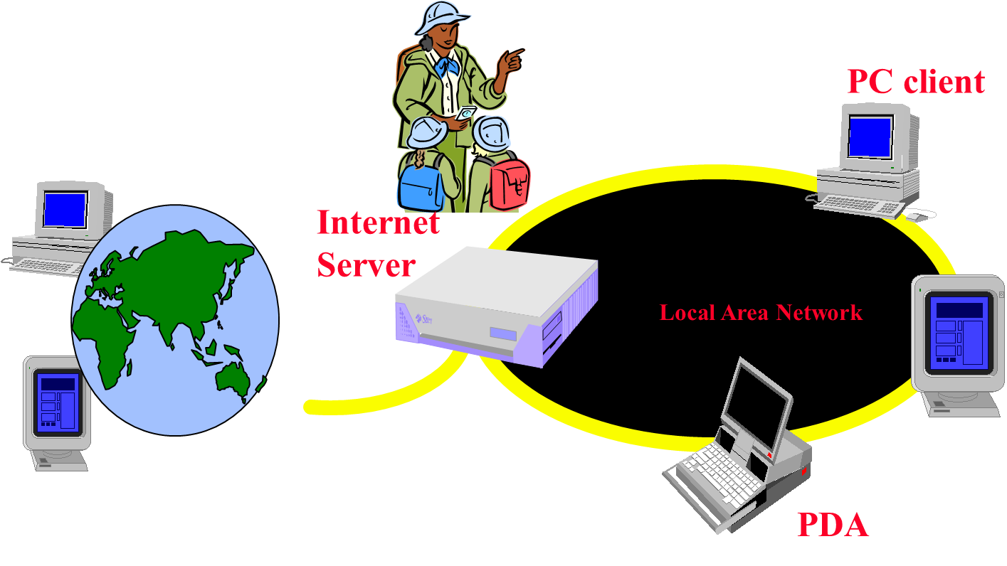
4.2. Internet Applications Serving Local and Remote Users

A communication channel can be described in terms of four attributes:
- Performance – dictated by the network latency and bandwidth
- Reliability
- Validity - a message put in the outgoing buffer is eventually delivered to the incoming message buffer
- Integrity – the message received is identical to the one sent, and no messages are delivered twice
- Ordering
- A channel is ordered if messages are delivered in the order in which they were sent
- A channel is ordered if messages are delivered in the order in which they were sent
- Synchronicity
- Synchronous – each message transmitted over a channel is received within a known bounded time
- Asynchronous – message transmission time is unbounded
4.3. The Internet protocol
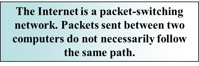
Every computer on the Internet has a unique identifier, its Internet address (IP address). The Internet protocol (IP) routes packets from one computer to another.
A router is a special-purpose computer which acts as an intermediary between a pair of communicating computers
An IP packet includes:
- The identity of the sender machine – i.e. it’s IP address
- The identity of the machine to which the packet should be delivered
- The packet contents – application data
The maximum size permitted for an IP packet is 64Kb:
- In practice, this is too much for many networks to deliver in one chunk and the IP packet must be broken down into fragments
- The IP protocol takes care of disassembling a packet into fragments and subsequently reassembling the IP packet
4.4. IP as a basis for a communication channel
Performance
- Depends on the underlying networks used
Reliability
- No validity guarantees
- Where an incoming message buffer is full (at the destination computer or any intermediate router), the packet will be dropped
- No integrity guarantees
- Packets may be corrupted as they travel through the network; any packet may arrive more than once at the destination
Ordering
- No ordering guarantees – a sequence of packets may take different routes, incurring different transmission times
Synchronicity
- Over a public network (e.g. the Internet) , asynchronous
- For a closed network, synchronous is possible
4.5. The characteristics of inter-process communication
Synchronous and asynchronous
- a queue associated with message destination, Sending process add message to remote queue, Receiving process remove message from local queue
- Synchronous: send and receive are blocking operations
- asynchronous: send is unblocking, receive could be blocking or unblocking (receive notification by polling or interrupt)
Message destination
- Internet address + local port
- service name: help by name service at run time
- location independent identifiers, e.g. in Mach
Reliability
- validity: messages are guaranteed to be delivered despite a reasonable number of packets being dropped or lost
- Integrity: messages arrive uncorrupted and without duplication
Ordering
- the messages be delivered in sender order
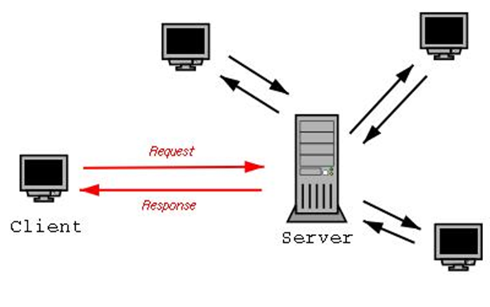
4.6. Elements of C-S Computing
Elements of C-S Computing

Processes follow protocol that defined a set of rules that must be observed by participants:
- How the data is exchange is encoded?
- How are events (sending, receiving) are synchronized (ordered) so that participants can send and receive in a coordinated manner?
Face-to-face communication, humans beings follow unspoken protocol based on eye contact, body language, gesture.
Client/sever model
Client asks (request) – server provides (response)
Typically: single server - multiple clients
The server does not need to know anything about the client
- even that it exists
The client should always know something about the server
- at least where it is located
Networking Basics
TCP/IP Stack
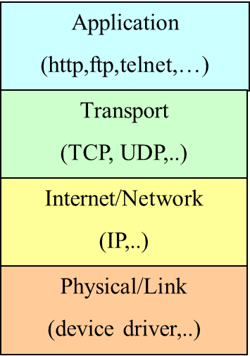
Physical/Link Layer
- Functionality for the transmission of signals, representing a stream of data from one computer to another.
Internet/Network Layer
- IP (Internet Protocols) – a packet of data to be addressed to a remote computer and delivered.
Transport Layer
- Functionalities for delivering data packets to a specific process on a remote computer.
- TCP (Transmission Control Protocol)
- UDP (User Datagram Protocol)
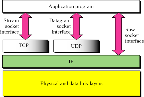
Programming Interface:
- Sockets
Applications Layer
- Message exchange between standard or user applications:
- HTTP, FTP, Telnet
- HTTP, FTP, Telnet
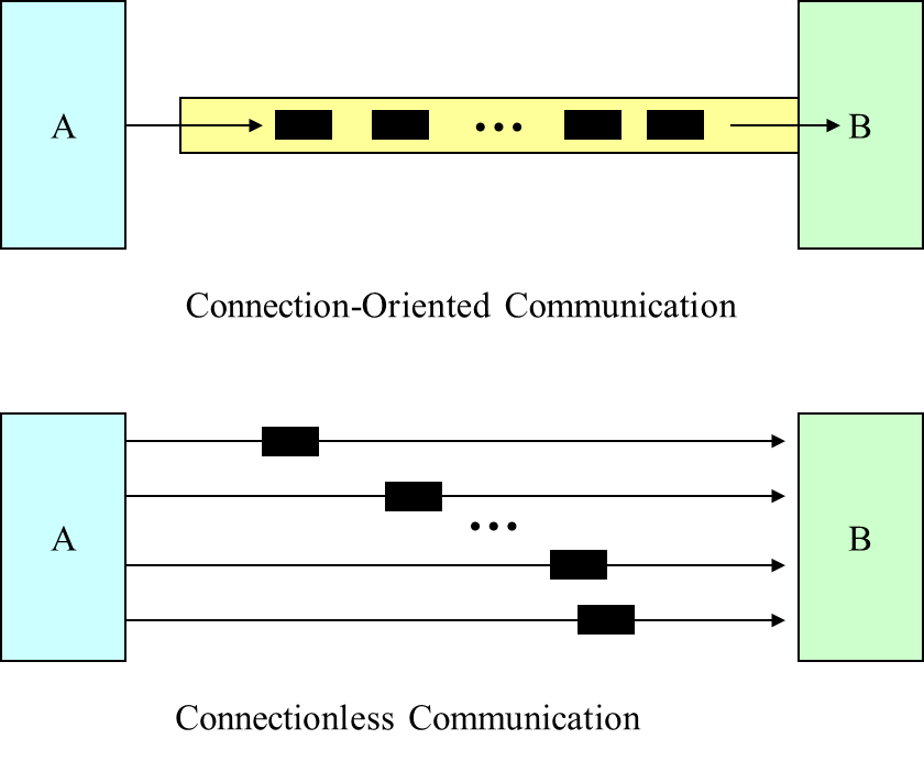
TCP (Transmission Control Protocol) is a connection-oriented communication protocol that provides a reliable flow of data between two computers. Example applications:
- HTTP
- FTP
- Telnet
UDP (User Datagram Protocol) is a connectionless communication protocol that sends independent packets of data, called datagrams, from one computer to another with no guarantees about arrival or order of arrival. Similar to sending multiple emails/letters to a friends, each containing part of a message.Example applications:
- Clock server
- Ping
4.7. Network Layering
The TCP and UDP protocols use ports to map incoming data to a particular process running on a computer.
Network
Layering
Layering
Makes it Easier
Application programmer
- Doesn’t need to send IP packets
- Doesn’t need to send Ethernet frames
- Doesn’t need to know how TCP implements reliability
Only need a way to pass the data down
- Socket is the API to access transport layer functions
What Lower Layer Need to Know?
We pass the data down. What else does the lower layer need to know?
How to identify the destination process?
- Where to send the data? (Addressing)
- What process gets the data when it is there? (Multiplexing)
Identify
the Destination
Addressing
- IP address
- hostname (resolve to IP address via DNS)
Multiplexing
- port
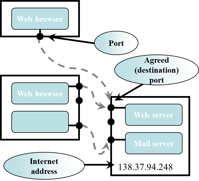
Understanding Ports
The TCP and UDP protocols use ports to map incoming data to a particular process running on a computer.
Port is represented by a positive (16-bit) integer value. Some ports have been reserved to support common/well known services:
- ftp 21/tcp
- telnet 23/tcp
- smtp 25/tcp
- login 513/tcp
User level process/services generally use port number value >= 1024.
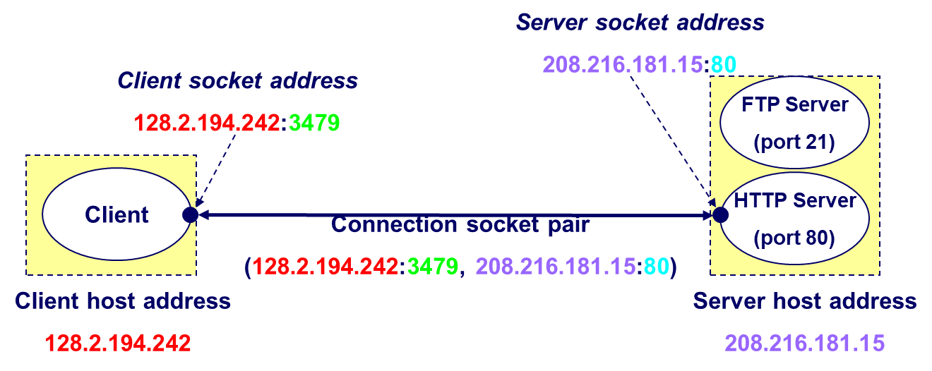
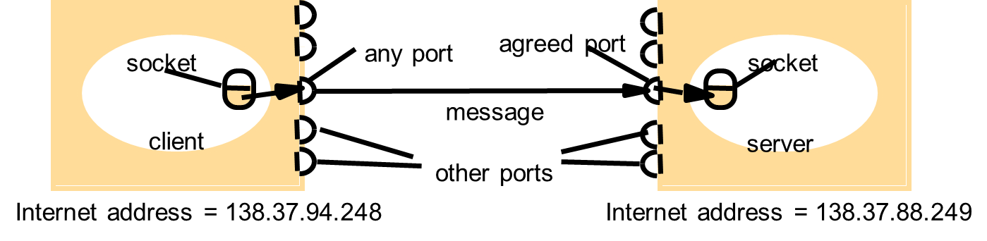
Ports
A port serves as a message source or destination
- With the Internet protocols, messages are sent to (Internet address, port) pairs
A local port can be bound to no more than one process. Processes may use multiple ports
Usage
of port-numbers
Standard applications use predefined port-numbers
- 21 - ftp
- 23 - telnet
- 80 - http
- 110 - pop3 (email)
- …
Other applications should choose between 1024 and 65535
- 4662 – eMule
- …
4.8. Sockets
Sockets
How to use sockets
Setup socket- Where is the remote machine (IP address, hostname)
- What service gets the data (port)
Send and Receive
- Designed just like any other I/O in unix
- send -- write
- recv -- read
Close the socket
Sockets provide an interface for programming networks at the transport layer. Network communication using Sockets is very much similar to performing file I/O. In fact, socket handle is treated like file handle. The streams used in file I/O operation are also applicable to socket-based I/O. Socket-based communication is programming language independent.
That means, a socket program written in Java language can also communicate to a program written in Java or non-Java socket program.
The
Socket API
A socket API provides a programming construct termed a socket. A process wishing to communicate with another process must create an instance, or instantiate, such a construct. The two processes then issue operations provided by the API to send and receive data.
The conceptual model of the socket API
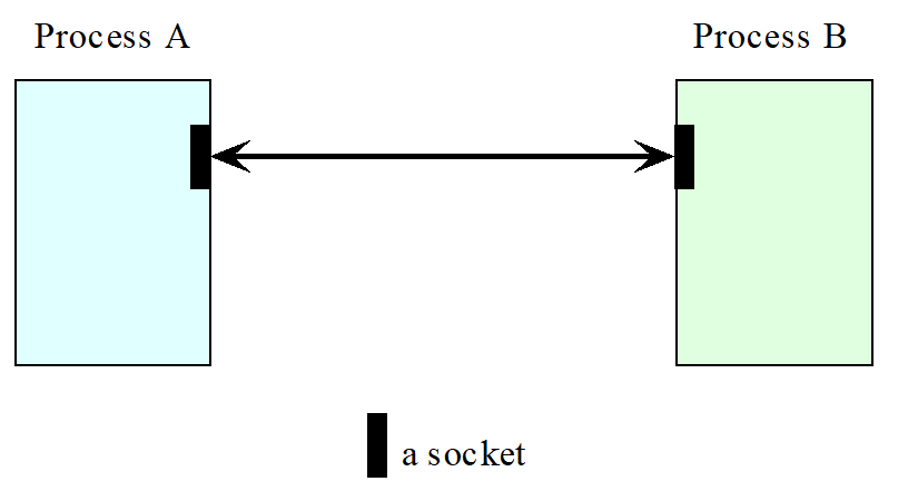
A socket is a programming abstraction which provides an endpoint for communication The receiver process’ socket must be bound to a local port and the Internet address of the computer on which the receiver runs. Messages sent to a particular Internet address and port number can be received only by a process whose socket is bound to that Internet address and port number. A socket is associated with a transport protocol – either TCP or UDP.
Endpoint for communication between processes. Both forms of communication (UDP and TCP ) use the socket abstraction.
Originate from BSD Unix :
- be present in most versions of UNIX
- be bound to a local port (216 possible port number) and one of the Internet address
- a process cannot share ports with other processes on the same computer
Socket
types
Datagram socket – using UDP
- Not sequenced
- Not reliable
- Not unduplicated
- Connectionless
- Border preserving
Stream socket – using TCP
- Sequenced
- Reliable
- Unduplicated
- Connection-oriented
- Not border preserving
Raw and others (extracurricular)
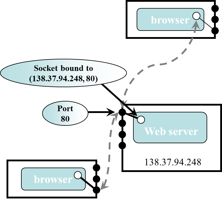
Socket
Communication
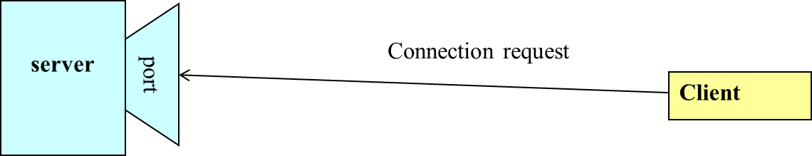
A server (program) runs on a specific computer and has a socket that is bound to a specific port. The server waits and listens to the socket for a client to make a connection request.
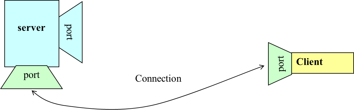
If everything goes well, the server accepts the connection. Upon acceptance, the server gets a new socket bounds to a different port. It needs a new socket (consequently a different port number) so that it can continue to listen to the original socket for connection requests while serving the connected client.
Sockets
and Java Socket Classes
A socket is an endpoint of a two-way communication link between two programs running on the network. A socket is bound to a port number so that the TCP layer can identify the application that data destined to be sent. Java’s .net package provides two classes:
- Socket – for implementing a client
- ServerSocket – for implementing a server
Connection-oriented
& Connectionless Datagram Socket
A socket programming construct can make use of either the UDP (User Datagram Protocol) or TCP (Transmission Control Protocol). Sockets that use UDP for transport are known as datagram sockets, while sockets that use TCP are termed stream sockets.
TCP
Vs. UDP Communication
Datagram sockets can support both connectionless and connection-oriented communication at the application layer.
This is so because even though datagrams are sent or received without the notion of connections at the transport layer, the runtime support of the socket API can create and maintain logical connections for datagrams exchanged between two processes.
The runtime support of an API is a set of software that is bound to the program during execution in support of the API.
4.9. Connection-oriented & Connectionless Datagram Socket
Connection-oriented & Connectionless Datagram Socket
Datagram sockets can support both connectionless and connection-oriented communication at the application layer.
- This is so because even though datagrams are sent or received without the notion of connections at the transport layer, the runtime support of the socket API can create and maintain logical connections for datagrams exchanged between two processes.
- The runtime support of an API is a set of software that is bound to the program during execution in support of the API.
The Java Datagram Socket API
In Java, two classes are provided for the datagram socket API:
- the DatagramSocket class for the sockets.
- the DatagramPacket class for the datagram exchanged.
A process wishing to send or receive data using this API must instantiate a DatagramSocket object, or a socket in short. Each socket is said to be bound to a UDP port of the machine on which the process is running. To send a datagram to another process, a sending process:
- Creates an object that represents the datagram itself. This object can be created by instantiating a DatagramPacket object which carries
- the payload data as a reference to a byte array, and
- the destination address (the host ID and port number to which the receiver’s socket is bound).
- Issues a call to a send method in the DatagramSocket object, specifying a reference to the DatagramPacket object as an argument.
In the receiving process, a DatagramSocket object must also be instantiated and bound to a local port, the port number must agree with that specified in the datagram packet of the sender.
To receive datagrams sent to the socket, the receiving process creates a DatagramPacket object which references a byte array and calls a receive method in its DatagramSocket object, specifying as argument a reference to the DatagramPacket object.
4.10. UDP datagram communication
UDP datagram communication
UDP datagrams are sent without acknowledgement or retries
Issues relating to datagram communication
- Message size: not bigger than 64k in size, otherwise truncated on arrival
- blocking: non-blocking sends (message could be discarded at destination if there is not a socket bound to the port ) and blocking receives (could be timeout)
- Timeout: receiver set on socket
- Receive from any: not specify an origin for messages
Failure model
- omission failure: message be dropped due to checksum error or no buffer space at sender side or receiver side
- ordering: message be delivered out of sender order
- application maintains the reliability of UDP communication channel by itself
TCP stream communication
The API to the TCP
- Provide the abstraction of a stream of bytes to which data may be written and from which data may be read
Hidden network characteristics
- message sizes
- lost messages
- flow control
- message duplication and ordering
- message destinations
Issues related to stream communication
- Matching of data items: agree to the contents of the transmitted data
- Blocking: send blocked until the data is written in the receiver’s buffer, receive blocked until the data in the local buffer becomes available
- Threads: server create a new thread when it accept a connection
Failure model
- Integrity and validity have been achieved by checksum, sequence number, timeout and retransmission in TCP protocol
- Connection could be broken due to unknown failures
- Can’t distinguish between network failure and the destination process failure
- Can’t tell whether its recent messages have been received or not
4.11. External data representation and marshaling introduction
Why does the communication data need external data representation and marshaling?
- Different data format on different computers, e.g., big-endian/little-endian integer order, ASCII (Unix) / Unicode character coding
How to enable any two computers to exchange data values?
- The values be converted to an agreed external format before transmission and converted to the local form on receipt
- The values are transmitted in the sender’s format, together with an indication of the format used, and the receipt converts the value if necessary
External data representation
- An agreed standard for the representation of data structures and primitive values
Marshaling (unmarshaling)
- The process of taking a collection of data items and assembling them into a form suitable for transmission in a message
- Usage: for data transmission or storing in files
Two alternative approaches
- CORBA’s common data representation / Java’s object serialization
4.12. CORBA’s Common Data Representation (CDR)
Represent all of the data types that can be used as arguments and return values in remote invocations in CORBA
15 primitive types
- Short (16bit), long(32bit), unsigned short, unsigned long, float, char, …
Constructed types
- Types that composed by several primitive types
A message example
The type of a data item is not given with the data representation in message
- It is assumed that the sender and recipient have common knowledge of the order and types of the data items in a message.
- For RMI and RPC, each method invocation passes arguments of particular types, and the result is a value of a particular type.
CORBA CDR for constructed types

4.13. Java object serialization
Serialization (deserialization)
- The activity of flattening an object or a connected set of objects into a serial form that is suitable for storing on the disk or transmitting in a message
- Include information about the class of each object and a version number
- Handles: references to other objects are serialized as handles
- Each object is written once only
- Example (n1)
- Make use of Java serialization
- ObjectOutputStream.writeObject, ObjectInputStream.readObject
The use of reflection
- Reflection : The ability to enquire about the properties of a class, and also enables classes to be created from their properties.
- Reflection makes it possible to do serialization (deserialization) in a completely generic manner
5. Chapter 5: Distributed Operating System
OVERVIEW- Introduction
- The
operating system layer
- Protection
- Processes
and threads
- Address
spaces
- Creation
of new process
- Threads
- Communication
and invocation
- Invocation
performance
- Asynchronous
operation
- Operating
system architecture
- Summary
5.1. Introduction
Network Operating System
- Examples: UNIX, Windows
- Built-in networking capability and can be used to access remote resources.
- Access is network-transparent for some types of resource.
- Example: distributed file system such as NFS, users have network-transparent access to files.
- Nodes retain autonomy in managing their own processing resources.
- User can remotely log into another computer and run processes there.
- OS manages processes running at its own node, but does not manage processes across the nodes.
- There are multiple system images, one per node.
Distributed operating system
- Users are never concerned with where their programs run, or the location of any resources.
- OS has control over all the nodes in the system
- It transparently locates new processes at whatever node suits its scheduling policies.
Middleware and network operating system
- There are no distributed operating system in general use.
- Two main reasons
- Users have much invested in their application software, which often meets their current problem-solving needs
- Users tend to prefer to have a degree of autonomy for their machines.
- These combination provides an acceptable balance between the requirement for autonomy and network transparent resource access on the other.
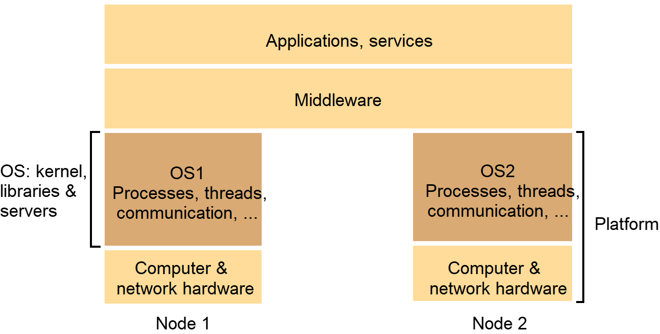
5.2. The operating system layer
- Middleware runs on a variety of OS – hardware combinations (platforms) at the nodes of a distributed system.
- OS running at a node provides
- abstraction of local hardware resources for processing, storage and communication.
- Middleware utilizes a combination of these local resources to implement its mechanisms for remote invocations between objects or processes at the nodes.
- Kernel and server processes are the components that manage resources and present clients with an interface to the resources.
- Encapsulation
- Provide a useful service interface to their resources – a set of operations that meet their clients’ needs.
- Details such as management of memory and devices used to implement the resources should be hidden from clients.
- Protection
- Resources require protection from illegitimate accesses
- Concurrent processing
- Client may share resources and access them concurrently.
- Resource managers are responsible for achieving concurrency transparency.
- Client access resources by making remote method invocations to a server object, or system calls to a kernel.
- A combination of libraries, kernels and servers may be called upon to perform the following invocation-related tasks:
- Communication
- Operation parameters and results have to be passes to and from resource managers, over a network or within a computer.
- Scheduling
- When an operation is invoked, its processing must be scheduled within the kernel or server.
Figure : System layers
Figure
: Core OS functionality
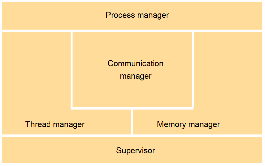
Core OS components
- Process manager
- Creation of and operation upon processes.
- Process is a unit of resource management, including an address space and one or more threads.
- Thread manager
- Thread creation, synchronization and scheduling.
- Communication manager
- Communication between threads attached to different processes on the same computer.
- Some kernels also support communication between threads in remote processes.
- Memory manager
- Management of physical and virtual memory.
- Supervisor
- Dispatching of interrupts, and other exceptions
- control of memory management unit and hardware caches.
- OS software is designed to be portable between computer architectures where possible.
- Majority of OS is coded in a high-level language such as C, C++ or Modula-3.
- Its facilities are layered so that machine-dependent components are reduced to a minimal bottom layer.
- Some kernels can executed on shared-memory multiprocessors.
- Several processors that share one or more modules of memory (RAM).
- Processors may also have their own private memory.
- Simplest and least expensive way to construct is by incorporating a circuit board holding a few (2 – 8) processors in a personal computer.
5.3. Protection
- Protect from illegitimate accesses for resources.
- Threats may come from maliciously contrived code.
- Example:
- Consider a file – two operations: read and write
- Ensure that each of the file’s two operations can be performed only by clients with the right to perform it.
- Example: Smith: read and right, Jones: read.
- Illegitimate access – Jones managed to perform a write operation on the file.
- A complete solution in a distributed system requires cryptographic techniques.
- Threats may also come from misbehaving client sidesteps the operation that a resource exports.
- Example: Smith or Jones managed to execute an operation that was neither read nor write.
- Smith managed to access the file pointer directly and construct a setFilePointerRandomly operation, that sets the file pointer to a random number.
- To protect resources from illegitimate invocations: use type-safe programming language such as Sing# (extension of C#) or Modula-3.
- In type-safe languages, no module may access a target module unless it has a reference to it – it cannot make up a pointer to it.
- Employ hardware support to protect modules from one another at the level of individual invocations, regardless of the language in which they are written – kernel.
- Kernels and protection
- The kernel is a program that is remains loaded from system initialization
- Its code is executed with complete access privileges for the physical resources on its host computer.
- It can control memory management unit and set the processor registers so that no other code may access the machine’s physical resources except in acceptable ways.
- Kernels and protection
- A kernel process executes with the processor in supervisor (privileged) mode.
- The kernel arranges that other processes execute in user (unprivileged) mode.
- The kernel sets up address spaces to protect itself and other processes from the accesses of an aberrant process.
- Address space – a collection of ranges of virtual memory locations with memory access rights applies such as read-only or read-write.
- A process cannot access memory outside its address space.
- The kernel provide processes with their required virtual memory layout.
- When a process executed application code, it executes in a distinct user-level address space for that application.
- When the same process executes kernel code, it executes in the kernel’s address space.
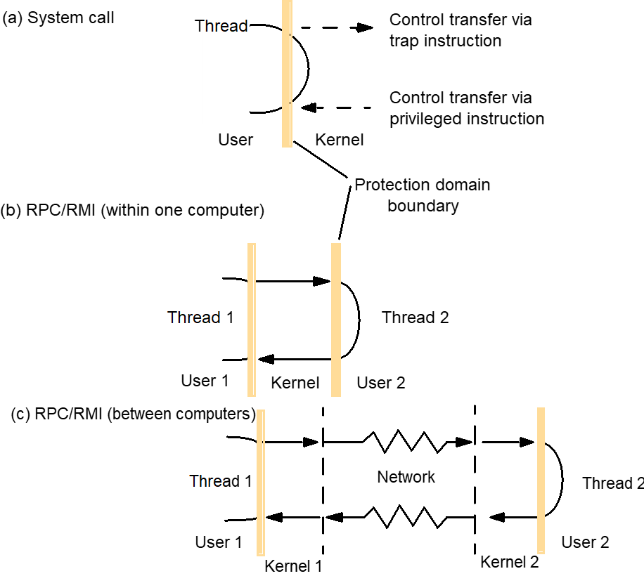
- The process can safely transfer from a user-level address space to the kernel’s address space via an operation such as an interrupt or a system call trap.
- Example of interrupt or a system call trap execution
- Implemented by a machine-level TRAP instruction.
- Puts the processor into supervisor mode and switches to the kernel address space.
- The hardware forces the processor to execute a kernel-supplied handler function, in order that no process may gain illicit control of the hardware.
- However, switching between address spaces may take many processor cycles, and a system call trap is a more expensive operation than a simple procedure or method call.
5.4. Processes and threads
Processes and threads- A process consists of an execution environment together with one or more threads.
- Execution environment
- unit of resource management
- A collection of local kernel-managed resources to which its threads have access.
- Consists of
- An address space
- Thread synchronization and communication resources such as semaphores and communication interfaces (example: sockets).
- Higher-level resources such as open files and windows.
- Expensive to create and manage, but several threads can share them.
- Represent the protection domain in which its threads execute.
- Threads can be created and destroyed dynamically, as needed.
- Thread - operation system abstraction of an activity.
- Multiple threads of execution
- Maximize the degree of concurrent execution between operations
- Enabling the overlap of computation with input and output.
- Enabling concurrent processing on multiprocessors.
- Helpful within servers, where concurrent processing of clients’ requests can reduce the tendency for servers to become bottlenecks.
- Execution environment provides protection from threads outside it.
- Certain kernels allow the controlled sharing of resources between execution environments residing at the same computer.
Address spaces
- A unit of management of a process’s virtual memory.
- Large (232 bytes or 264 bytes)
- Consists of one or more regions, separated by inaccessible areas of virtual memory.
- A region is an area of contiguous virtual memory that is accessible by the threads of the owning process.
- Regions do not overlap.
- Each region is specified by the following properties:
- Its extent (lowest virtual address and size)
- Read/write/execute permissions for the process’s threads
- Whether it can be grown upwards or downwards.
Figure : Address space
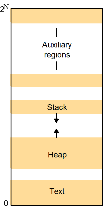
- Gaps are left between regions to allow for growth.
- Generalization of the UNIX address space, which has three regions:
- A fixed → unmodifiable text region containing program code
- A heap → part of which is initialized by values stored in the program’s binary file, which is extensible towards higher virtual addresses
- A stack → which is extensible towards lower virtual addresses.
- The provision of an indefinite number of regions is motivated by several factors;
- To support separate stack for each thread.
- Make it possible to detect attempts to exceed the stack limits and to control each stack’s growth.
- Unallocated virtual memory lies beyond each stack region, and attempts to access to these will cause an exception
- To enable files in general
- not just the text and data sections of binary files – to be mapped into the address space.
- Mapped file – accessed as an array of bytes in memory
- To support separate stack for each thread.
- Shared memory region
- Same physical memory as one or more regions belonging to other address spaces.
- Libraries
- a single of copy of the library code can be shared by being mapped as a region in the address spaces of processes that require it.
- Kernel
- kernel code and data are mapped into every address space at the same location.
- When a process makes a system call or an exception occurs, there is no need to switch to a new set of address mappings.
- Data sharing and communication
- it can be considerably more efficient for the data to be shared by being mapped as regions in both address spaces than by being passed in messages between them.
Creation
of new process
- The design of the process-created mechanism has to take into account the utilization of multiple computers.
- Two independent aspects:
- The choice of a target host
- The creation of an execution environment
- Choice of process host
- The choice is a matter of policy.
- Location policy
- Determines which node should host a new process selected for transfer.
- Depends on the relative loads of nodes.
- The choice of target host is transparent to programmer and the user.
- Static
- Operate without regard to the current state of the system
- Based on mathematical analysis aimed at optimizing a parameter such as overall process throughput.
- Maybe deterministic – node A should always transfer process to node B
- Maybe probabilistic – node A should transfer processes to any of nodes B – E at random
- Adaptive
- Apply heuristics to make their allocation decisions, based on unpredictable runtime factors such as a measure of the load on each node.
- Load-sharing systems maybe
- Centralized
- Load manager component collects information about the nodes and use it to allocate new processes to nodes.
- Hierarchical
- Several load managers, organized in a tree structure.
- Managers make process allocation decisions as far down the tree as possible, but managers may transfer processes to one another, via a common ancestor, under certain load conditions.
- Decentralized
- Nodes exchange information with one another directly to make allocation decisions.
- Example: The Spawn system considers nodes to be ‘buyers’ and ‘sellers’ of computational resources and arranges them in a (decentralized) ‘market economy’.
- Centralized
- Load-sharing algorithms
- Sender-initiated
- The node that requires a new process to be created is responsible for initiating the transfer decision.
- Initiates a transfer when its own load crosses a threshold.
- Receiver-initiated
- A node whose load is below a given threshold advertises its existence to other nodes so that relatively loaded nodes can transfer work to it.
- Migratory load-sharing systems
- Can shift load at any time
- Process migration mechanism – transfer of an executing process from one node to another.
- Sender-initiated
- Creation of a new execution environment
- Two approaches to defining and initializing the address space of a newly created process.
- First approach address space is of a statically defined format.
- Second approach address space can be defined with respect to an existing execution environment.
- UNIX: the newly created child process physically shares the parent’s text region and has heap and stack regions that are copies of the parent’s in extent (as well as in initial contents).
- This scheme has been generalized so that each region of the parent process maybe inherited by (or omitted from) the child process.
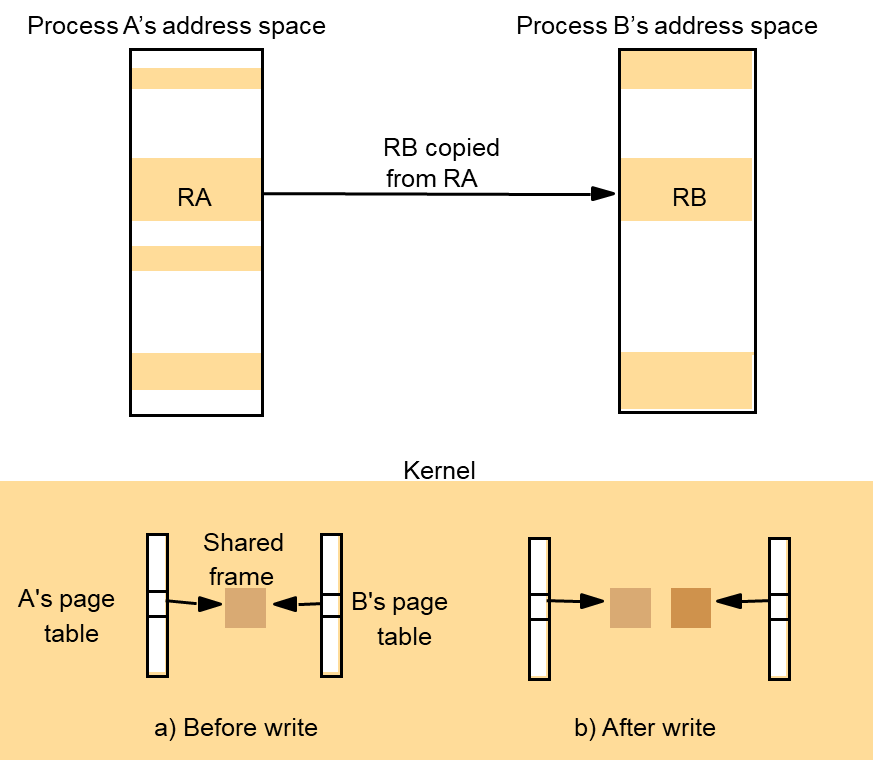
Figure
: Copy-on-write
5.5. Threads
- Architectures for multi-threaded servers
- The worker pool architecture
- The server creates a fixed pool of ‘worker’ threads to process the requests when it starts up.
- The module marked ‘receipt and queuing’ is typically implemented by an ‘I/O’ thread, which receives requests from a collection of sockets or ports and places them on a shared request queue for retrieval by the workers.
- There is sometimes a requirement to treat the requests with varying priorities.
- Example: corporate web server could prioritize request processing according to the class of customer from which the request derives.
- Multiple queues for varying priorities in decreasing priority.
- But, high level of switching between the I/O and worker thread as they manipulated the shared queue.
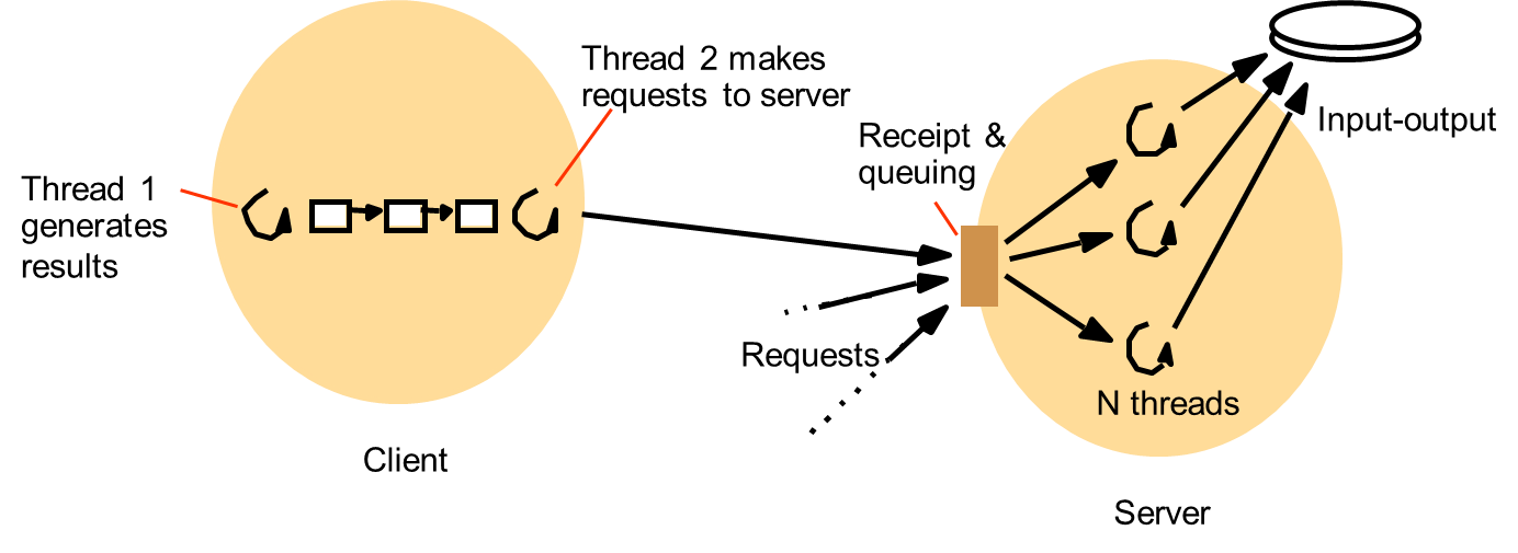
Figure : Client and server with threads
- Thread-per-request architecture
- I/O thread spawns a new worker thread for each request
- Worker destroys itself when it has processed the request against its designated remote object.
- The threads do not contend for a shared queue.
- Throughput can be maximized because the I/O thread can creates as many workers as there are outstanding requests.
- But, overhead of the thread creation and destruction operations.
- Thread-per-connection architecture
- Associates a thread with each connection
- The server creates a new worker thread when a client makes a connection and destroys the thread when the client closes the connection.
- Client may make many requests over the connection, targeted at one or more remote objects.
Figure : Alternative server threading architectures
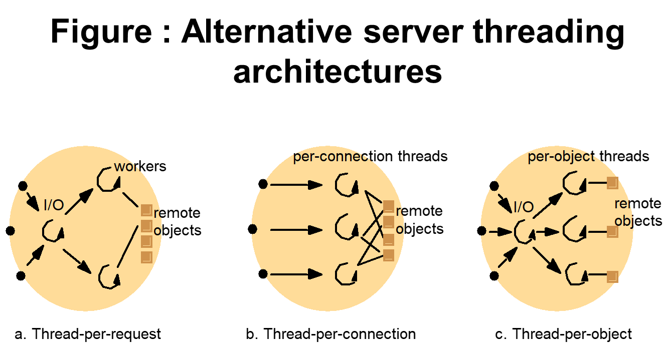
- Thread-per-object architecture
- Associates a thread with each remote object.
- An I/O thread receive requests and queues them for the workers, but this time there is a per-object queue.
- For the last two architectures, the server benefits from lower thread-management overhead compared with the thread-per-request architecture.
- But, client maybe delayed while a worker thread has several outstanding requests but another thread has no work to perform.
- Threads within clients
- Can be useful for clients as well as servers.
- Client process with two threads.
- First thread: generates results to be passed to a server by remote method invocation, but does not require a reply. (Remote method invocation blocks the caller.)
- Second thread: performs the remote method invocations and blocks while the first thread is able to continue computing further results.
- First thread places its results in buffers, which are emptied by the second thread.
- First thread is only blocked when all the buffers are full.
- Thread versus multiple processes
- Threads are cheaper to create and manage than processes
- Resource sharing can be achieved more efficiently between threads than between processes because threads share an execution environment.
- Switching to a different thread within the same process is cheaper than switching between threads belonging to different processes.
- Threads within a process may share data and other resources conveniently and efficiently compared to separate processes.
- But, threads within a process are not protected from one another.
Figure : State associated with execution environments and threads
- Thread programming
- Concurrent programming
- Much threads programming is done in a conventional language, such as C with threads library.
- POSIX Threads standard IEEE 1003.1c-1995, known as pthreads, has been adopted recently.
- Some languages provide direct support for threads, including Ada95 [Burns and Wellings 1998], Modula-3 [Harbison 1992] and Java [Oaks and Wong 1999].
- Java provides method for creating threads, destroying them and synchronizing them.
Figure : Java thread constructor and management methods
- Thread synchronization
- Main difficult issues: sharing of objects and the techniques used for thread coordination and cooperation.
- Each thread’s local variables in methods are private to it.
- However, threads are not given private copies of static (class) variables or object instance variables.
- Race conditions might arise when threads manipulate data structures such as shared queues concurrently.
- Java provides the synchronized keyword for programmers to designate the monitor construct for thread coordination.
- The monitor’s guarantee is that at most one thread can execute within it at any time.
Figure : Java thread synchronization calls

- Thread scheduling
- Preemptive scheduling
- A thread maybe suspended at any point to make way for another thread, even when the preempted thread would otherwise continue running.
- Non-preemptive scheduling
- A thread runs until it makes a call to the threading system, then the system may deschedule it and schedule another thread to run.
- Race condition can be avoided.
- But, cannot take the advantage of multiprocessor, since they run exclusively.
- Care must be taken over long-running sections of code that do not contain calls to the threading system.
- Unsuited to real-time applications.
- Preemptive scheduling
- Thread implementation
- Many kernels provide native support for multi-threaded processes, including Windows, Linux, Solaris, Mach and Mac OS X.
- When no kernel support for multi-threaded processes is provided, a user-level thread implementation suffers from the following problems:
- The threads within a process cannot take advantage of a multiprocessor.
- A thread that takes a page fault blocks the entire process and all threads within it.
- Threads within different processes cannot be scheduled according to a single scheme of relative prioritization.
- Thread implementation
- User-level threads implementations, have significant advantages over kernel-level implementations:
- Certain thread operations are significantly less costly.
- Given that the thread-scheduling module is implemented outside the kernel, it can be customized or changed to suit particular application requirements.
- Many more user-level threads can be supported than could reasonably be provided by default by a kernel.
- User-level threads implementations, have significant advantages over kernel-level implementations:
5.6. Communication and invocation
iii. Packet initialization
iv. Thread scheduling and context switching
v. Waiting for acknowledgements:
iii. Packet initialization
iv. Thread scheduling and context switching
v. Waiting for acknowledgements:
Communication primitives
- Some kernels designed for distributed systems have provided communication primitives tailored to the types of invocation.
- Example:
- Amoeba provides doOperation, getRequest and sendReply as primitives.
- Amoeba, the V system and Chorus provide group communication primitives.
- Middleware provides RMI over UNIX’s connected (TCP) sockets, then a client must make two communication system calls (socket write and read) for each remote invocation.
- Over Amoeba, it require only a single call to doOperation.
- Despite the widespread use of TCP and UDP sockets provided by common kernels, research continues to be carried out into lower-cost communication primitives in experimental kernels.
Protocols and openness
- One of the main requirements of the operating system is to provide standard protocols that enable internetworking between middleware implementations on different platforms.
- By contrast, the designers of the Mach 3.0 and Chorus kernels (as well as L4) decided to leave the choice of networking protocols entirely open.
- These kernels provide message passing between local processes only, and leave network protocol processing to a server that runs on top of the kernel.
- Protocols are normally arranged in a stack of layers.
- Many operating systems allow new layers to be integrated statically.
- By contrast, dynamic protocol composition is a technique whereby a protocol stack can be composed on the fly to meet the requirements of a particular application, and to utilize whichever physical layers are available given the platform’s current connectivity.
- Example: a web browser running on a notebook computer should be able to take advantage of a wide area wireless link while the user is on the road, and then a faster Ethernet connection when the user is back in the office.
- Support for protocol composition appeared in the design of the UNIX Streams facility [Ritchie 1984], in Horus [van Renesse et al. 1995] and in the x-kernel [Hutchinson and Peterson 1991], construction of configurable transport protocol CTP on top of the Cactus system [Bridges et al. 2007].
Invocation performance
- Invocation performance is a critical factor in distributed system design.
- The more designers separate functionality between address spaces, the more remote invocations are required.
- Invocation costs
- Calling a conventional procedure or invoking a conventional method, making a system call, sending a message, remote procedure calling and remote method invocation are all examples of invocation mechanisms.
- Each mechanism causes code to be executed outside the scope of the calling procedure or object.
- Each involves, in general, the communication of arguments to this code and the return of data values to the caller.
Figure : Invocations between address spaces
- Invocation over the network
- A null RPC (and similarly, a null RMI) is defined as an RPC without parameters that executes a null procedure and returns no values.
- Its execution involves an exchange of messages carrying some system data but no user data.
- Much of the observed RPC delay is accounted by the actions of the operating system kernel and user-level RPC runtime code and not from the total network transfer time.
- Null invocation costs are important because they measure a fixed overhead, the latency.
Figure : RPC delay against parameter size

- RPC throughput is also a concern when data has to be transferred in bulk.
- Steps in an RPC
- A client stub marshals the call arguments into a message, sends the request message and receives and unmarshals the reply.
- At the server, the worker thread calls the appropriate server stub.
- The server stub unmarshals the request message, calls the designated procedure and marshals and send the reply.
- Main components accounting for remote invocation delay, beside network transmission times:
- Marshalling → Marshalling and unmarshaling, which involve copying and converting data, create a significant overhead as the amount of data grows.
- Data copying
- Even after marshalling, message data is copied several times:
- Across the user-kernel boundary, between the client or server address space and kernel buffers;
- Across each protocol layer
- Between the network interface and kernel buffers
- Transfer between network interface and main memory are usually handled by direct memory access (DMA).
- Even after marshalling, message data is copied several times:
- Packet initialization
- Involves initializing protocol headers and trailers, including checksums.
- Thread scheduling and context switching
- Several system calls are made during an RPC, as stubs invoke the kernel’s communication operations
- One or more server threads is scheduled.
- If the operating system employs a separate network manager process, then each Send involves a context switch to one of its threads.
- Waiting for acknowledgements:
- The choice of RPC protocol may influence delay, particularly when large amounts of data are sent.
- Memory sharing
- Bershad et al. [1990] report a study that showed that, in the installation examined, most cross-address-space invocation took place within a computer and not, as might be expected in a client-server installation, between computer.
- Bershad et al. developed a more efficient invocation mechanism for the case of two processes on the same machine called lightweight RPC (LRPC).
- It would be more efficient to use shared memory regions for client-server communication, with a different (private) region between the server and each of its local clients.
- Such as region contains one or more A stacks.
- Instead of RPC parameters being copied between the kernel and user address spaces involved, the client and server are able to pass arguments and return values directly via an A stack.
- The same stack is used by the client and server stubs.
- In LRPC, arguments are copied once: when they are marshalled onto the A stack.
- In an equivalent RPC, they are copied four times:
- from the client stub’s stack onto a message;
- from the message to a kernel buffer,
- from the kernel buffer to a server message, and
- from the message to the server stub’s stack.
- Instead of setting up one or more threads, which then listen on ports for invocation requests, the server exports a set of procedures that it is prepared to have called.
- Threads in local processes may enter the server’s execution environment as long as they start by calling one of the server’s exported procedures.
Figure : A lightweight remote procedure call
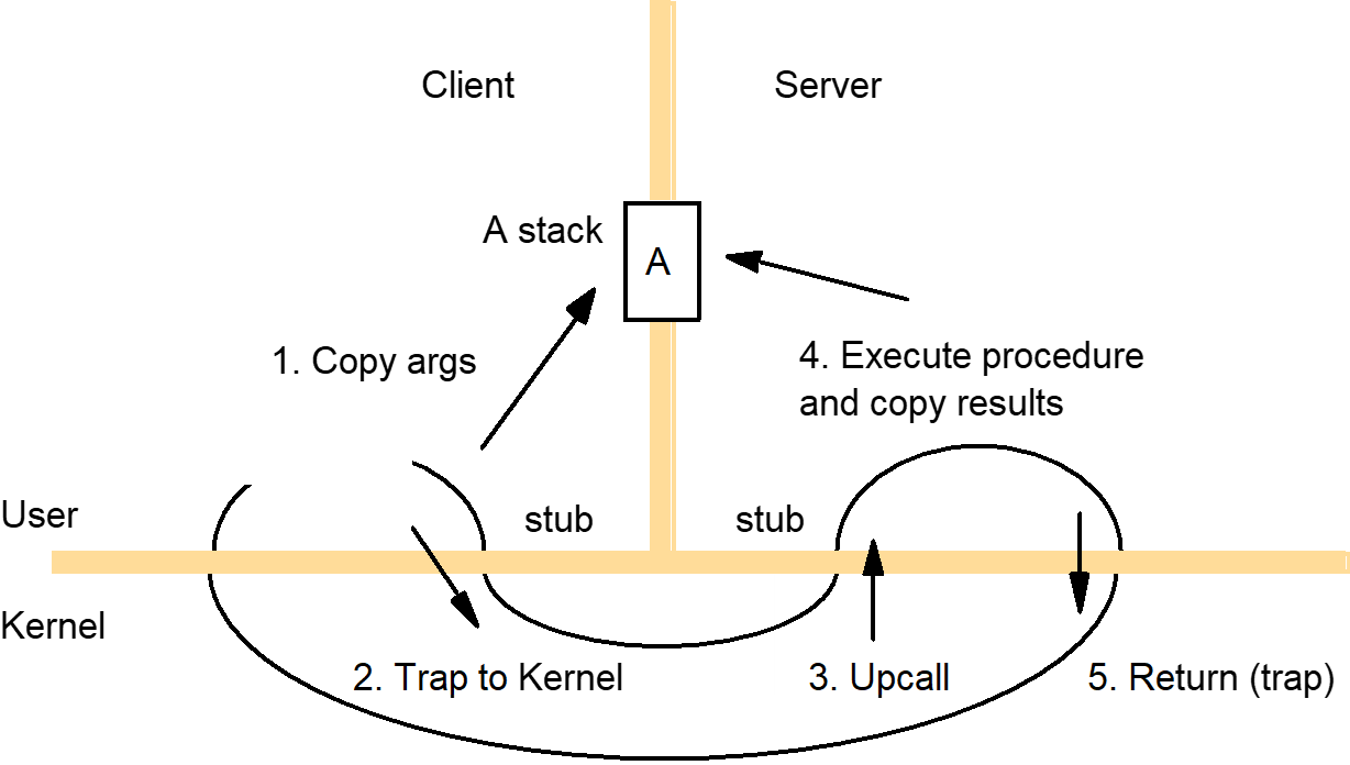
5.7. Asynchronous operation
Asynchronous
operation
Making invocation concurrently
- The middleware provides only blocking invocations, but the application spawns multiple threads to perform blocking invocations concurrently.
- Example is a web browser.
- A web page typically contains several images and may contain many.
- The browser does not need to obtain the images in a particular sequence, so it makes several concurrent requests at a time.
- That way, the time taken to complete all the image requests is typically lower than the delay that would result from making the requests serially.
- Not only is the total communication delay less, in general, but the browser can overlap computation such as image rendering with communication.
Figure : Times for serialized and concurrent invocations

Asynchronous invocations
- It is made with a non-blocking call, which returns as soon as the invocation request message has been created and is ready for dispatch.
- The client uses a separate call to collect the result of the invocation.
- Example: Mercury communication system [Liskov and Shrira 1988]
- An asynchronous operation returns an object called a promise.
- Eventually, when the invocation succeeds or failed, the Mercury system places the status and any return values in the promise.
- The caller uses the claim operation to obtain the result from the promise.
- The claim operation blocks until the promise is ready, whereupon it returns the results or exceptions from the call.
- The ready operation is available for testing a promise without blocking – it returns true or false according to whether the promise is ready or blocked.
Operating
system architecture
An open distributed system should make it possible to:
- Run only that system software at each computer that is necessary for it to carry out its particular role in the system architecture –
- system software requirements can vary between, for example, mobile phones and server computers, and loading redundant modules wastes memory resources;
- Allow the software (and the computer) implementing any particular service to be changed independently of other facilities;
- Allow for alternatives of the same service to be provided, when this is required to suit different users or applications;
- Introduce new services without harming the integrity of the existing ones.
Monolithic kernels
- Massive – it performs all basic operating system functions and takes up in the order of megabytes of code and data – and that it is undifferentiated, i.e. it is coded in a non-modular way.
- To a large extent, it is intractable – altering any individual software component to adapt it to changing requirements is difficult.
- Example: UNIX operating system kernel, Sprite network operating system [Ousterhout et al. 1988]
- Can contain some server processes that execute within its address space.
Microkernels
- The microkernel appears as a layer between the hardware layer and a layer consisting of major system components called subsystems.
- Middleware may use the facilities of the microkernel directly, or uses a language runtime support subsystem, or a higher-level operating system interface provided by an operating system emulation subsystem.
Figure : Monolithic kernel and microkernel
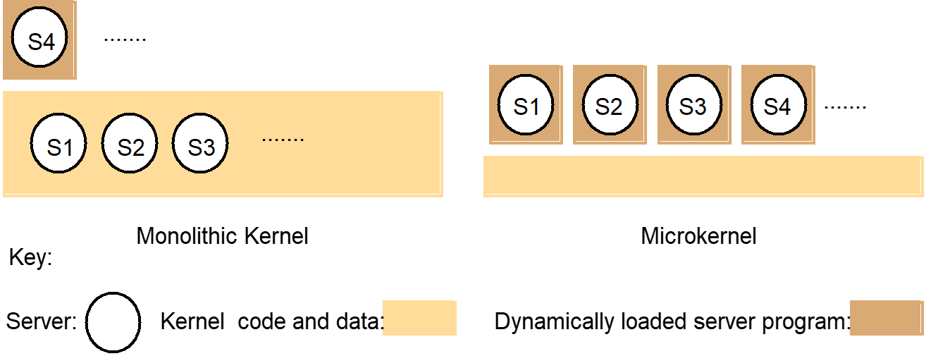
Comparison
- Advantages of microkernel-based operating system
- Extensibility
- Ability to enforce modularity behind memory protection boundaries
- Relatively small, more likely to be free of bugs
- Advantages of monolithic kernel
- Relative efficiency with which operations can be invoked.
- Windows employs a combination of both [Custer 1998], but its functionality is not designed to be routinely replaceable.
5.8. Summary
Summary
- Process & thread
- A Process consists of multiple threads and an execution environment
- Multiple-threads: cheaper concurrency, take advantage of multiprocessors for parallelism
- Remote invocation cost
- Marshalling & unmarshalling
- data copying
- packet initialization
- thread scheduling and context switching
- Network transmission
- OS architecture
- Monolithic kernel & microkernel
6. Chapter 6: Coordination and Agreement
TOPIC OVERVIEW- Introduction
- Distributed Mutual Exclusion
- Algorithms
for mutual exclusion
- Elections
Algorithm
- Ring-based
Elections
- Bully-based
Elections Algorithm
- Coordination
and agreement in group communication
- Consensus and related problems
6.1. Introduction
Introduction
- Assumptions:
- Each pair of processes is connected by reliable channels.
- No process failure implies a threat to the other processes’ ability to communicate.
- In any particular interval of time, communication between some processes may succeed while communication between others is delayed.
- Example: failure of a router between two networks -> network partition
- Eventually any failed link or router will be repaired or circumvented.
- The processes may not all be able to communicate at the same time.
- The processes fail only by crashing.
Figure 6.1: A network partition
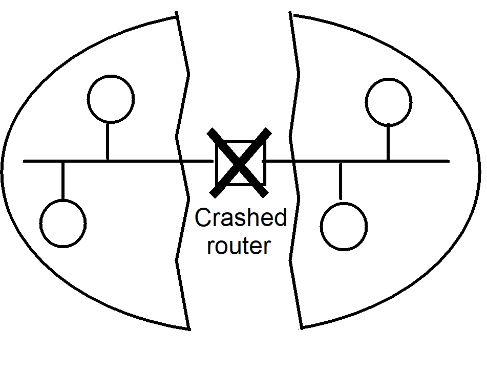
- Failure detector
- Service that processes queries about whether a particular process has failed.
- (a) Unreliable failure detectors
- Produce one of two values: Unsuspected or Suspected
- May or may not accurately reflect whether the process has actually failed.
- Unsuspected -> the detector has recently received evidence suggesting that the process has not failed
- Suspected -> the failure detector has some indication that the process may have failed
- (b) Reliable failure detector
- Always accurate in detecting a process’s failure
- Unsuspected or Failed
- Failed -> the detector has determined that the process has crashed.
- Algorithm for unreliable failure detector
- Each process p sends a ‘p is here’ message to every other process.
- It does this every T seconds.
- Maximum message transmission time: D seconds
- If the local failure detector at process q does not receive a ‘p is here’ message within T + D seconds of the last one, then it reports to q that p is Suspected.
- If it subsequently receives a ‘p is here’ message, then it reports to q that p is OK.
- In a synchronous system, the failure detector can be made into a reliable one.
- D is not an estimate but an absolute bound on message transmission times; the absence of a ‘p is here’ message within T + D seconds indicates that p has crashed.
6.2. Distributed Mutual Exclusion
Distributed
Mutual Exclusion
- Mutual exclusion is required to prevent interference and ensure consistency when accessing the shared resources.
- Distributed mutual exclusion – based solely on message passing.
- In some cases, shared resources are managed by servers that also provide mechanisms for mutual exclusion.
- UNIX systems provide file-locking service, implemented by the daemon lockd, to handle locking requests from clients.
- When there is no server, and a collection of peer processes must coordinate their accesses to shared resources amongst themselves.
- It is useful to have a generic mechanism for distributed mutual exclusion – one that is independent of the particular management scheme.
- Mutual exclusion algorithms
Algorithms
for mutual exclusion
- A system of N processes pi, i = 1, 2, …, N, that do not share variables.
- The processes access common resources, but they do so in a critical section.
- Assume there is only one critical section.
- Assume that the system is asynchronous, that processes do not fail and that message delivery is reliable.
- Application-level protocol for executing a critical section:
- enter() // enter critical section – block if necessary
- resourceAccesses() // access shared resources in critical section
- exit() // leave critical section – other processes may now enter
- Essential requirements for mutual exclusion:
- ME1: (safety) – at most one process may execute in the critical section (CS) at a time.
- ME2: (liveness) – request to enter and exit the critical section eventually succeed.
- ME3: (-> ordering) – if one request enter the CS happened-before another, then entry to the CS is granted in that order.
- Evaluation of the performance for mutual exclusion algorithms is according to the following criteria:
- The bandwidth consumed, which is proportional to the number of messages sent in each entry and exit operation;
- The client delay incurred by a process at each entry and exit operation;
- The algorithm’s effect upon the throughput of the system.
- Using synchronization delay between one process exiting the critical section and the next process entering it
- The throughput is greater when the synchronization delay is shorter.
- Also assumes that the client processes are well behaved and spend a finite time accessing resources within their critical sections.
- The central server algorithm
- Employ a server that grants permission to enter the critical section.
- To enter a critical section, a process sends a request message to the server and awaits a reply from it.
- The reply constitutes a token signifying permission to enter the critical section.
- If no other process has the token at the time of the request, then the server replies immediately, granting the token.
- If the token is currently held by another process, then the server does not reply, but queues the request.
- When a process exits the critical section, it sends a message to the server, giving it back the token.
- If the queue of waiting processes is not empty, then the server chooses the oldest entry in the queue, removes it and replies to the corresponding process.
Figure 6.2: Server managing a mutual exclusion token for a set of processes
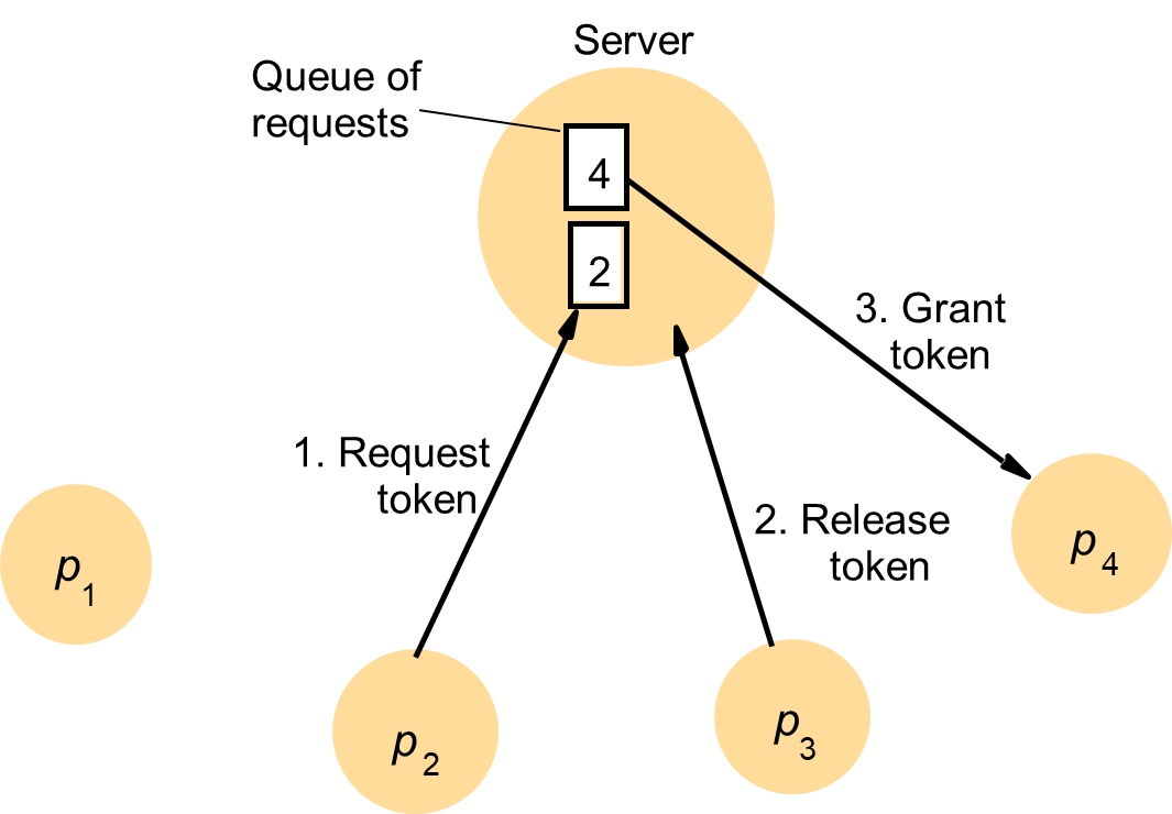
- Performance of this algorithm
- Entering the critical section – even when no process currently occupies it – takes two messages (a request followed by a grant) and the delays the requesting process by the time required for this round-trip.
- Exiting the critical section takes one release message.
- Assuming asynchronous message passing, the release message does not delay the exiting process.
- Server may become a performance bottleneck for the system as a whole.
- Synchronization delay -> time taken for a round-trip: a release message to the server, followed by a grant message to the next process to enter the critical section.
- A ring-based algorithm
- Arrange mutual exclusion between the N processes without requiring an additional process.
- Arrange the processes in a logical ring.
- Requires only that each process pi has a communication channel to the next process in the ring, p(i+1)modN.
- Exclusion is conferred by obtaining a token in the form of a message passed from process to process in a single direction around the ring.
- If a process does not require to enter the critical section when it receives the token, then it immediately forwards the token to its neighbour.
- A process that requires the token waits until it receives it, but retains it.
- To exit the critical section, the process sends the token on to its neighbour.
- This algorithm continuously consumes network bandwidth (except when a process is inside the critical section):
- The processes send messages around the ring even when no process requires entry to the critical section.
- The delay experienced by a process requesting entry to the critical section is between 0 message (when it has just received the token) and N messages (when it has just passed on the token).
- To exit the critical section, required only one message.
- Synchronization delay between one process’s exit from the critical section and the next process’s entry is anywhere from 1 to N message transmissions
Figure 6.3: A ring of processes transferring a mutual exclusion token
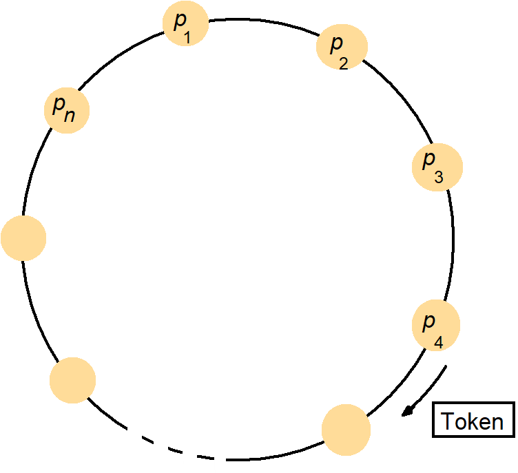
- An algorithm using multicast and logical clocks
- Implement mutual exclusion between N peer processes that is based upon multicast.
- Processes that require entry to a critical section multicast a request message, and can enter it only when all the other processes have replied to this message.
- The processes p1, p2, …, pN bear distinct numeric identifiers.
- They are assumed to possess communication channels to one another.
- Message requesting entry are of the form <T, pi>, where T is the sender’s timestamp and pi is the sender’s identifier.
- Each process records its state of being outside the critical section (RELEASED), wanting entry (WANTED) or being in the critical section (HELD) in a variable state.
Figure 6.4: Ricart and Agrawala’s algorithm
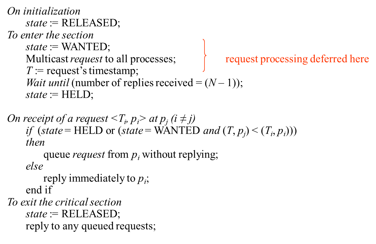
- If a process requests entry and the state of all other processes is RELEASED, then all processes will reply immediately to the request and the requester will obtain entry.
- If process is in the state HELD, that that process will not reply to requests until it has finished with the critical section, and so the requester cannot gain entry.
- If two or more processes request entry at the same time, then whichever process’s request bears the lowest timestamp will be the first to collect N – 1 replies, granting it entry next.
- Gaining entry takes 2(N – 1) messages in this algorithm:
- N – 1 to multicast the request, followed by N – 1 replies.
- It is a more expensive algorithm, in terms of bandwidth consumption.
- Synchronization delay is only one message transmission time.
Figure 6.5: Multicast synchronization
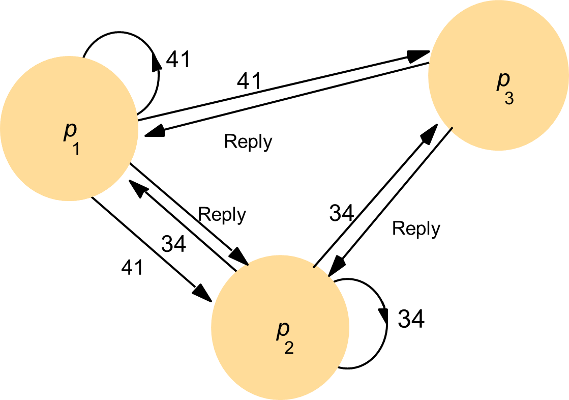
6.3. Distributed Mutual Exclusion II


Figure 6.6:Maekawa’s algorithm


- Fault tolerance
- Main points in evaluating the above algorithms with respect to fault tolerance are:
- What happens when message are lost?
- What happens when a process crashes?
- None of the algorithms above would tolerate the loss of messages, if the channels were unreliable.
- The ring-based cannot tolerate a crash failure of any single process.
- Maekawa’s algorithm can tolerate some process crash failures
- If a crashed process is not in a voting set that is required, then its failures will not affect the other processes.
- The central server algorithm can tolerate the crash failure of a client process that neither holds nor has requested the token.
- The Ricart and Agrawala algorithm can be adapted to tolerate the crash failure of such a process, by taking it to grant all requests implicitly.
- Even with a reliable failure detector, care is required to allow for failures at any point (including during a recovery procedure), and to reconstruct the state of the processes after a failure has been detected.
- Main points in evaluating the above algorithms with respect to fault tolerance are:
6.4. Elections Algorithm
Elections Algorithm
- Need to find one process that is the coordinator
- Assume
- Each process has a unique identifier (for example, network address)
- One process per machine
- Every process knows the process number of every other process
- Processes don’t know which processes are down and which ones are still running
- End result of the algorithm: all processes agree on who is the new coordinator/leader
- Bully algorithm & Ring Algorithm

Ring-based
Elections
Does NOT use a token
Assume
- processes are ordered
- each process knows its successor and the successor’s successor, and so on (needed in case of failures)
Process P detects that the coordinator is dead
- sends an ELECTION message to its successor
- includes its process number in the message
- each process that receives it, adds its own process number and then forwards it to its successor
- eventually it gets back that message, now what does it do?


Figure
6.7: A ring-based election in progress
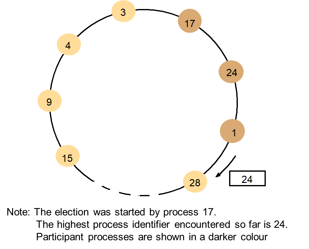
A process notices that coordinator is not responding
- it starts an election (any process can start one)
Election algorithm
- P sends an ELECTION message to processes with higher numbers
- If no one responds, P wins the election
- If some process with higher process number responds
- P’s job is done, that process takes over
- the receiver sends an OK message to P
- receiver starts an election process
Eventually all processes give up, except one
This process sends out a message saying that it is the new “COORDINATOR”
A process that was down, when it comes back up starts a new election of its own
The bully algorithm
- Allows processes to crash during an election
- Assumes that message delivery between processes is reliable
- Assumes that the system is synchronous
- Uses timeouts to detect a process failure
- Assumes that each process knows which processes have higher identifiers, and that it can communicate with all such processes.
- Three types of message
- Election message – to announce an election
- Answer message – response to an election message
- Coordinator message – to announce the identity of the elected process – the new ‘coordinator’.
- A process begins an election when it notices, through timeouts, that the coordinator has failed.
- Upper bound on the time between sending a message to another process and receiving a response:
- T = 2Ttrans + Tprocess
Ttrans: maximum message transmission delay
Tprocess: maximum delay for processing a message
- T = 2Ttrans + Tprocess
- The process that knows it has the highest identifier can elect itself as the coordinator simply by sending a coordinator message to all processes with lower identifiers.
- A process with a lower identifier can begin an election by sending an election message to those processes that have a higher identifier and awaiting answer messages in response.
- If none arrives within time T, the process considers itself as the coordinator and sends a coordinator message to all processes with lower identifiers.
- Otherwise, the process waits a further period T’ for a coordinator message to arrive from the new coordinator.
- If none arrives, it begins another election.
- If a process pi receives a coordinator message, it sets its variable electedi to the identifier of the coordinator contained within it.
- If a process receives an election message, it sends back an answer message and begins another election – unless it has begun one already.
- When a process is started to replace a crashed process, it begins an election.
- If it has the higher process identifier, then it will decide that it is the coordinator and announce this to the other processes.
- Thus, it will become the coordinator, even though the current coordinator is functioning.
Figure 6.8: The bully algorithm
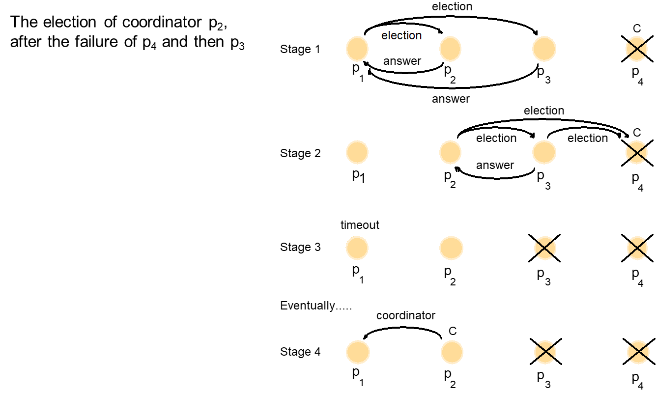
6.5. Coordination and agreement in group communication
System model:
- Contains a collection of processes, which can communicate reliably over one-to-one channels.
- Processes may fail only by crashing.
- The processes are members of groups.
- To simplify, processes is member of at most one group at a time.
- Operation multicast(g, m) sends the message m to all members of the group g of processes.
- Operation deliver(m) that delivers a message sent by multicast to the calling process.
- Every message m carries the unique identifier of the process sender(m) that sent it and the unique destination group identifier group(m).
- Assume that processes do not lie about the origin or destinations of messages.
Basic multicast
- A correct process will eventually deliver the message, as long as the multicaster does not crash.
- Straightforward way to implement B-multicast is to use a reliable one-to-one send operation:
To B-multicast(g, m): for each process p ∈ g, send(p, m);
On receive(m) at p: B-deliver(m) at p.
Reliable multicast
- All correct processes in the group must receive a message if any of them does.
- Integrity: A correct process p delivers a message m at most once.
- Validity: If a correct process multicasts m, then it will eventually deliver m.
- Agreement: If a correct process delivers message m, then all other correct processes in group(m) will eventually deliver m.
- If a process that multicasts a message crashes before it has delivered it, then it is possible that the message will not be delivered to any process in the group; but if it is delivered to some correct process, then all other correct processes will deliver it.
Figure 6.9: Reliable multicast algorithm
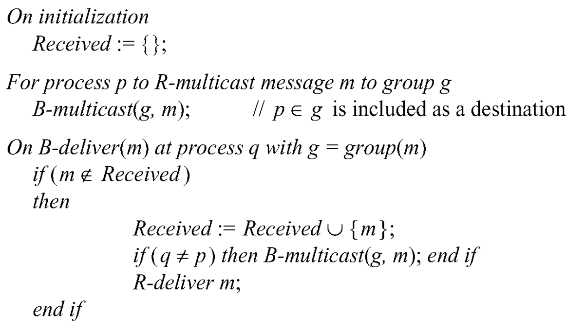
- The algorithm satisfies the validity property, since a correct process will eventually B-deliver the message to itself.
- By the integrity property of the underlying communication channels used in B-multicast, the algorithm also satisfies the integrity property.
- Agreement follows from the fact that every process B-multicasts the message to the other processes after it has B-delivered it.
- If a process does not R-deliver the message, then this can only be because it never B-delivered it.
- That in turn can only be because no other correct process B-delivered it either; therefore none will R-deliver it.
Uniform properties
- The agreement above refers only to the behaviour of correct processes – processes that never fail.
- If a process was not correct and crashed after it had R-delivered a message, since any process that R-delivers the message must first B-multicast it, it follows that all correct processes will still eventually deliver the message.
- Uniform agreement: If a process, whether it is correct or fails, delivers message m, then all correct processes in group(m) will eventually deliver m.
- It is useful in applications where a process may take an action that produces an observable inconsistency before it crashes.
Ordered multicast
- The basic multicast algorithm delivers messages to processes in an arbitrary order, due to arbitrary delays in the underlying one-to-one send operations.
- To simplify, the orderings assume that any process belongs to at most one group only.
- Common ordering requirements:
- FIFO ordering: If a correct process issues multicast(g, m) and then multicast(g, m’), then every correct process that delivers m’ will deliver m before m’.
- Causal ordering: If multicast(g, m) -> multicast(g, m’), where -> is the happened-before relation induced only by messages sent between the members of g, then any correct process that delivers m’ will deliver m before m’.
- Total ordering: If a correct process delivers message m before it delivers m’, then any other correct process that delivers m’ will deliver m before m’.
- The definitions of ordered multicast do not assume or imply reliability.
Figure 6.11: Total, FIFO and causal ordering of multicast messages
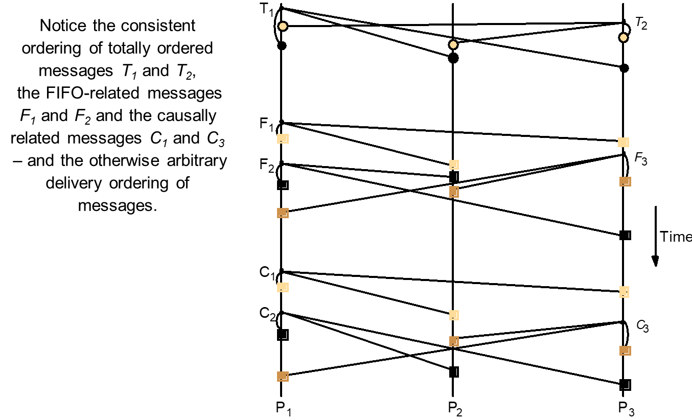
Overlapping groups
- The preceding definitions considered only non-overlapping groups.
- Global FIFO ordering: If a process issues multicast(g, m) and then multicast(g’, m’), then every correct process in g ∩ g’ that delivers m’ will deliver m before m’.
- Global causal ordering: If multicast(g, m) -> multicast(g’, m’), where -> is the happened before relation induced by any chain of multicast messages, then any correct process in g ∩ g’ that delivers m’ will deliver m before m’.
- Pairwise total ordering: If a correct process delivers message m sent to g before it delivers m’ sent to g’, then any other correct process in g ∩ g’ that delivers m’ will deliver m before m’.
- Global total ordering: Let ‘<‘ be the relation of ordering between delivery events. We require that ‘<‘ obeys pairwise total ordering and that it is acyclic.
6.6. Consensus and related problems
The problem is for processes to agree on a value after one or more of the processes has proposed what that value should be.
System model
- A collection of processes pi (i = 1, 2, …, N) communicating by message passing.
- Important requirement: consensus to be reached even in the presence of faults.
- Assume that communication is reliable but the processes may fail.
- To reach consensus, every process pi begins in the undecided state and proposes a single value vi, drawn from a set D (i = 1, 2, …, N).
- The processes communicate with one another, exchanging values.
- Each process then sets the value of a decision variable di.
- In doing so, it enters the decided state, in which is may no longer change di (i = 1, 2, …, N).
Figure 6.16: Consensus for three processes
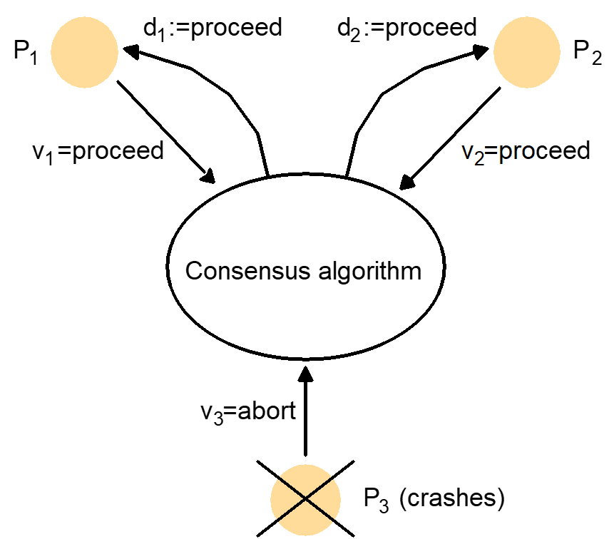
The requirements of a consensus algorithm:
- Termination: Eventually each correct process sets its decision variable.
- Agreement: The decision value of all correct processes is the same
If pi and pj are correct and have entered the decided state, then di = dj (i,j = 1, 2, …, N)
- Integrity: If the correct processes all proposed the same value, then any correct process in the decided state has chosen that value.
Consider a system in which processes cannot fail.
- Processes are collect into a group and have each process reliably multicast its proposed value to the members of the group.
- Each process waits until it has collected all N values (including its own).
- It then evaluates the function majority(v1, v2, …, vN), which returns the value that occurs the most often among its arguments.
If processes can crash, this introduces the complication of detecting failures.
- It is not immediately clear that a run of the consensus algorithm can terminate.
If processes can fail in arbitrary (Byzantine) ways, then faulty processes can in principle communicate random values to the others.
- Correct processes must compare what they have received with what other processes claim to have received.
- The Byzantine generals problem
Differs from consensus in that a distinguished process supplies a value that the others are to agree upon, instead of each of them proposing a value.
Requirements:
- Termination: Eventually each correct process sets its decision variable.
- Agreement: The decision value of all correct processes is the same
If pi and pj are correct and have entered the decided state, then di = dj (i,j = 1, 2, …, N)
Integrity: If the commander is correct, then all correct processes decide on the value that the commander proposed.
Interactive consistency
- Every process proposes a single value.
- The goal of the algorithm is for the correct processes to agree on a vector of values, one for each process.
- Example: the goal could be for each of a set of processes to obtain the same information about their respective states.
- The requirements:
- Termination: Eventually each correct process sets its decision variable.
- Agreement: The decision vector of all correct processes is the same.
- Integrity: If pi is correct, then all correct processes decide on vi as the ith component of their vector.
7. Chapter 7: Transaction and Concurrency Control
TOPIC OVERVIEW- Introduction
- Transactions
- Concurrency control
- Nested
transactions
- Locks
- Flat
and nested distributed transactions
- Atomic
commit protocols
- Concurrency
control in distributed transactions
7.1. Introduction
Simple synchronization (without transactions)
- Server is performed on behalf of different clients and may sometimes interfere with one another.
- The use of threads allows operations from multiple clients to run concurrently and possibly access the same objects.
- The use of synchronized keyword from Java ensure that only one thread at a time can access an object.
- If one thread invokes a synchronized method on an object, then that object is effectively locked, and another thread that invokes one of its synchronized methods will be blocked until the lock is released.
- It forces the execution of threads to be separated in time.
Enhancing client operation by synchronization of server operations
- This scheme prevent threads from interfering with one another.
- But, some applications require a way for threads to communicate with each other.
- Java wait and notify allow threads to communicate with one another.
- wait – the thread call wait on an object suspend itself and to allow another thread to executed a method of that object.
- notify – to inform any thread waiting on that object that it has changed some of its data
- Without the ability of synchronize, client might need to told to try again later and this will involve in polling the server and the server carrying out extra requests.
- It is also potentially unfair as other clients may make their requests before the waiting client tries again.
1. Failure model for transactions
- Failures of disks, servers and communication
- Claim that the algorithms work correctly in the presence of predictable faults, but no claims are made about their behaviour when a disaster occurs.
- The model states:
- Failures of disks
- Writes to permanent storage may fail, either by writing nothing or by writing a wrong value.
- File storage may decay.
- Reads from permanent storage can be detected (by a checksum) when a block of data is bad.
2. Failures of servers
- Servers may crash occasionally.
- When a crashed server is replaced by a new process, its volatile memory is first set to state in which it knows none of the values from before the crash.
- After that it carries out a recovery procedure using information in permanent storage and obtained from other processes to set the values of objects.
- When a processor is faulty, it is made to crash so that it is prevented from sending erroneous messages and from writing wrong values to permanent storage – can’t produce arbitrary failures.
- Crashes can occur at any time; may occur during recovery.
3. Failures of communication
- There may be arbitrary delay before a message arrives.
- A message may be lost, duplicated or corrupted.
- The recipient can detect corrupted messages using a checksum.
- Both forged messages and undetected corrupt messages are regarded as disasters.
7.2. Transactions
Transactions originate from database management systems.
- Transaction is an execution of a program that accesses a database.
Transactional file servers
- Transaction is an execution of a sequence of a client requests for file operations.
- Transaction consists of the execution of a sequence of client requests.
- From client’s point of view, a transaction is a sequence of operations that forms a single step, transforming the server data from one consistent state to another.
Transaction can be provided as a part of middleware.
- CORBA provides the specification for Object Transaction Service with IDL interfaces allowing clients’ transactions to include multiple objects at multiple servers.
Figure 1: A client’s banking transaction

Atomic transaction
- All or nothing:
- A transaction either completes successfully, in which case the effects of all of its operations are recorded in the objects, or (if it fails or is deliberately aborted) has no effect at all.
- Failure atomicity – the effects are atomic even when the server crashes
- Durability – after a transaction has completed successfully, all its effects are saved in permanent storage.
- Isolation:
- Each transaction must be performed without interference from other transactions.
- The intermediate effects of a transaction must not be visible to other transactions.
- ACID (atomicity, consistent, isolation, durability) properties
- ACID (atomicity, consistent, isolation, durability) properties
- Objects must be recoverable
- To support the requirement for failure atomicity and durability
- When a server process crashes unexpectedly due to hardware fault or a software error, the changes due to all completed transactions must be available in permanent storage so that when the server is replaced by a new process, it can recover the objects to reflect the all-or-nothing effect.
- By the time a server acknowledges the completion of client’s transaction, all of the transaction’s changes to the objects must have been recorded in permanent storage.
- Server must synchronize the operations to ensure that the isolation requirement is met.
- Doing this by performing the transactions serially – one at a time, in some arbitrary order.
- Transactions are allowed to execute concurrently if this would have the same effect as serial execution – serially equivalent or serializable.
Transaction capabilities can be added to servers of recoverable objects.
- Each transaction is created and managed by a coordinator, which implements the Coordinator interface.
- The coordinator gives each transaction an identifier (TID).
- Client invokes openTransaction method to introduce a new transaction – TID is allocated and returned.
- At the end of a transaction, the client invokes the closeTransaction method to indicates its end – all of the recoverable objects accessed by the transaction should have saved.
- If the client wants to abort a transaction, it invokes abortTransaction method – all of its effects should be removed.
- A transaction is achieved by cooperation between a client program, some recoverable objects and a coordinator.
- Client specifies the sequence of invocations on recoverable objects, with the TID.
Figure 2: Operations in Coordinator interface
When transactions are provided as middleware, TID can be passed implicitly between openTransaction and closeTransaction or abortTransaction.
- CORBA Transaction Service
When the client makes a closeTransaction request
- If it has progressed normally, the reply states that the transaction is committed – all changes requested in the transaction are permanently recorded and that any future transactions that access the same data will see the results of all of the changes made during the transaction.
- Transaction may have to abort – conflicts with another transaction or crashing of a process or computer
- Recoverable objects and the coordinator must ensure that none of its effects are visible to future transactions, either in the objects or in their copies in permanent storage.
- The client abort it (abortTransaction)
- Server aborts it.
Server actions related to process crashes
- If a server process crashes unexpectedly
- The server process will be replaced.
- The new process aborts any uncommitted transactions and uses a recovery procedure to restore the value of the objects to the values produced by the most recently committed transaction.
- To deal with a client that crashes unexpectedly during a transaction, servers give each transaction an expiry time and abort any transaction that has not completed before its expiry time.
Client actions related to server process crashes
- If a server crashes during transaction in progress, the client will become aware when one of the operations returns an exception after a timeout.
- If a server crashes and is then replaced during the progress of a transaction, the transaction will no longer be valid and the client must be informed via an exception to the next operation.
Figure 3: Transaction life histories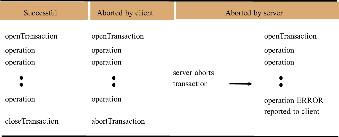
7.3. Concurrency control
The lost update problem
Example: bank accounts A, B and C, whose balances are $100, $200 and $300 respectively.
Transaction T transfers an amount from account A to B.
- Transaction U transfers an amount from account C to B.
- The amount transferred is calculated to increase the balance of B by 10%.
- The net effects on account B of executing the transactions T and U should be to increase the balance of account B by 10% twice, so the final value is $242.
- If transactions T and U run concurrently as in the following figure, U’s update is lost because T overwrites it without seeing it.
- Both transactions have read the old value before either writes the new value.
Figure 5: The lost update problem
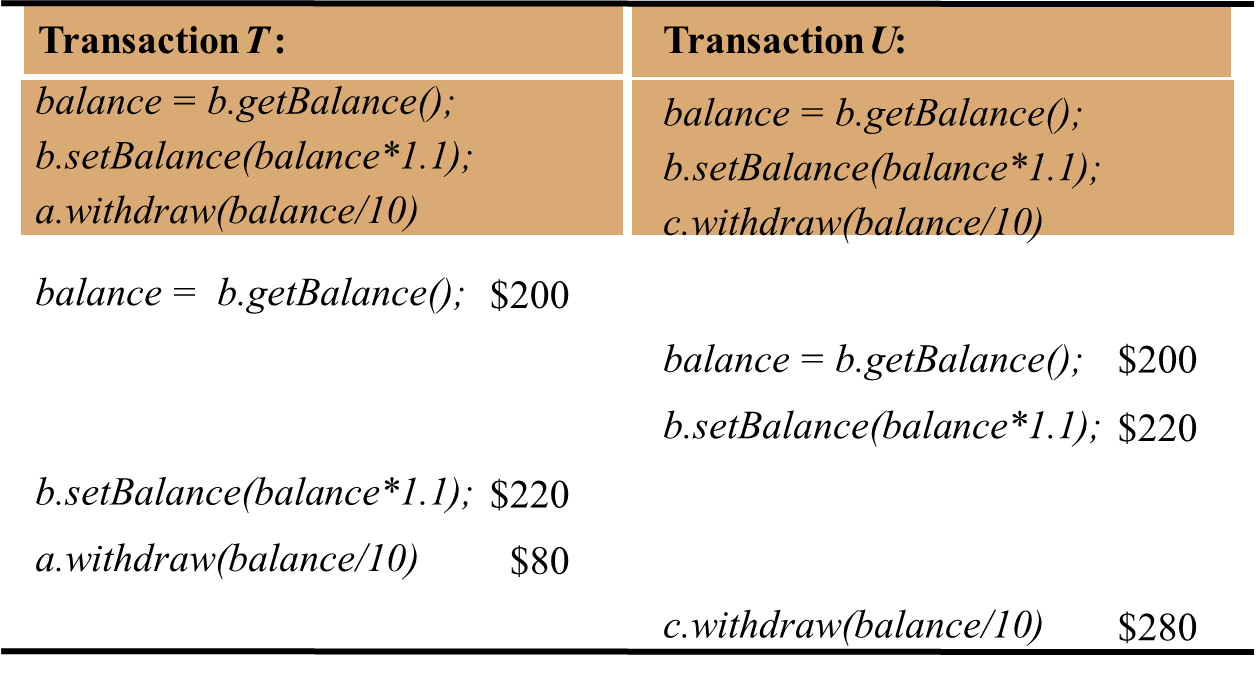
Inconsistent retrievals problem
- Example: Transaction V transfers a sum from account A to B and transaction W invokes the branchTotal method to obtain the sum of the balances of all the accounts in the bank.
- The balances of the two bank accounts, A and B are both initially $200.
- The result of branchTotal includes the sum of A and B as $300, which is wrong.
- W’s retrievals are inconsistent because V has performed only the withdrawal part of a transfer at the time the sum is calculated.
Figure 6: The inconsistent retrievals problem
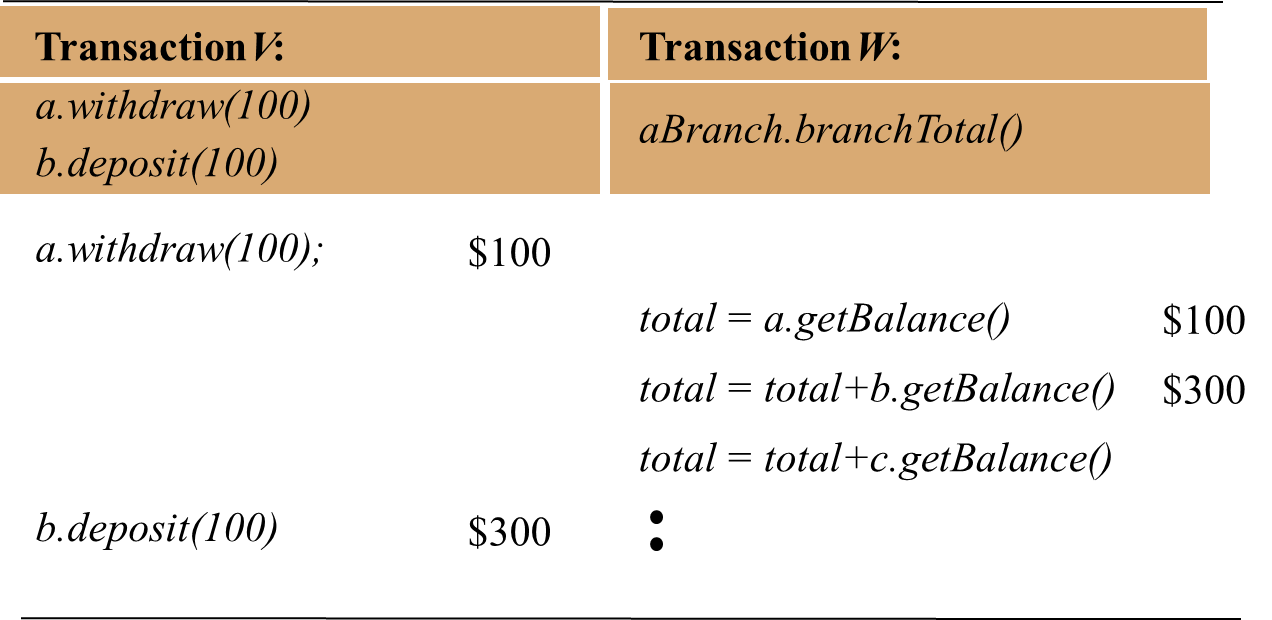
Serial equivalence
- An interleaving of the operations of the transactions in which the combined effect is the same as if the transactions had been performed one at a time in some order is a serially equivalent interleaving.
- It can be used to solve the lost update problem as shown in the following figure.
- The interleaving operations that affect the shared account B are actually serial.
- Transaction T does all its operations on B before transaction U does.
- Another interleaving of T and U that has this property is one in which transaction U completes its operations on account B before transaction T starts.
Figure 7: A serially equivalent interleaving of T and U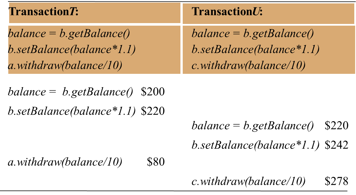
It also can be used to solve the inconsistent retrievals problem.
- Based on the example on transaction V is transferring a sum from account A to B and transaction W is obtaining the sum of all the balances.
- The inconsistent retrievals problem occur when a retrieval transaction runs concurrently with an update transaction.
- It cannot occur if the retrieval transaction is performed before or after the update transaction.
- A serially equivalent interleaving of a retrieval transaction and an update transaction
Figure 8: A serially equivalent interleaving of V and W
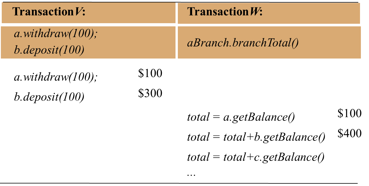
Conflicting operations
- A pair of operations conflicts mean that their combined effect depends on the order in which they are executed.
- Consider a pair of operations: read and write.
- read: accesses the value of an object
- write: changes the value of an object
- Conflict rule for read and write are given in the following figure.
- For two transactions to be serially equivalent, it is necessary and sufficient that all pairs of conflicting operations of the two transactions be executed in the same order at all of the objects they both access.
- Consider the following example for the transactions T and U:
- T:x = read(i); write(i, 10); write(j, 20);
- U:y = read(j); write(j, 30); z = read(i);
Figure 9: Read and write operation conflict rules
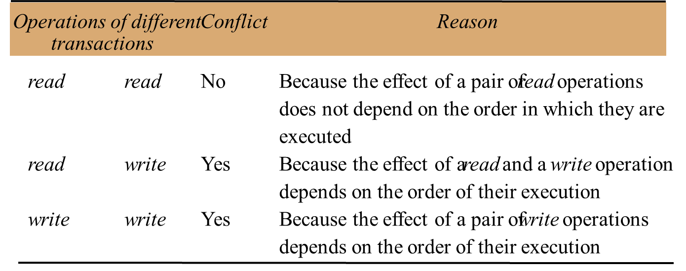
Figure 10: A non-serially equivalent interleaving of operations of transactions T and U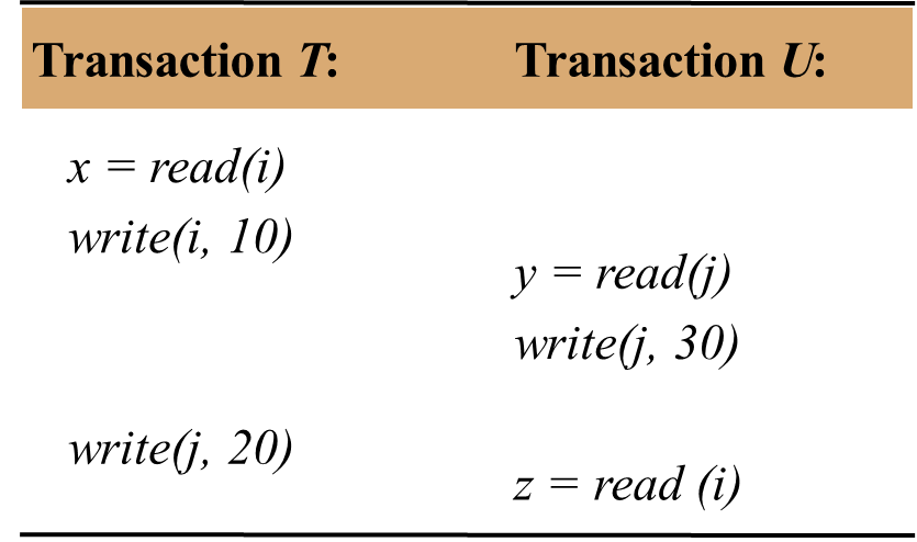
From the Figure 10, each transaction’s access to objects i and j is serialized with respect to one another, because T makes all of its accesses to i before U does and U makes all of its accesses to j before T does.
But the ordering is not serially equivalent, because the pairs of conflicting operations are not done in the same order at both objects.
Serially equivalent orderings require one of the following two conditions:
- 1. T accesses i before U and T accesses j before U.
- 2. U accesses i before T and U accesses j before T.
7.4. Recoverability from aborts
Servers must record all the effects of committed transactions and none of the effect of aborted transactions.
The following present the problems associated with aborting transactions (in the context of the banking example).
Dirty reads
- Caused by the interaction between a read operation in one transaction and an earlier write operation in another transaction on the same object.
Recoverability of transactions
- If transaction has committed after it has seen the effects of a transaction that subsequently aborted, the situation is not recoverable.
- Strategy is to delay commits until after the commitment of any other transactions whose uncommitted state has been observed.
Figure 11: A dirty read when transaction T aborts
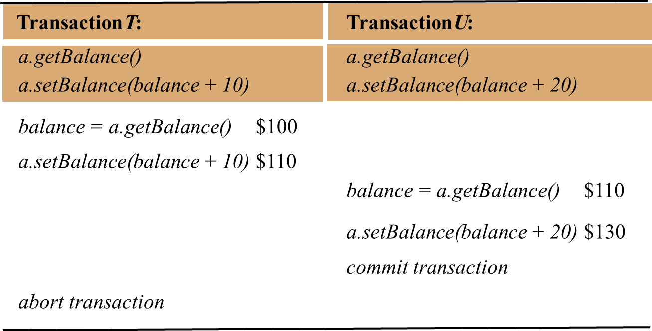
Cascading aborts
- In Figure 11, suppose that transaction U delays committing until after T aborts.
- U must abort as well.
- But, if any other transactions have seen the effects due to U, they too must be aborted.
- To avoid cascading aborts, transactions are only allowed to read objects that were written by committed transactions.
- Any read operation must be delayed until other transactions that applied a write operation to the same object have committed or aborted.
Premature writes
- Related to write operations on the same object belonging to different transactions.
- Consider two setBalance transactions, T and U, on account A.
- Before transactions, the balance of account A was $100.
- T set the balance to $105 and U set the balance to $110.
- If U aborts and T commits, the balance should be $105.
- Some database system implement the abort action by restoring ‘before images’ of all the writes of a transaction.
- ‘before image’ of T’s write is $100 and ‘before image’ of U’s write is $105.
- If U aborts, we get the correct balance of $105.
- U commits and then T aborts, balance should be $110, but ‘before image’ of T’s write is $100, we get the wrong balance of $100.
- T aborts and then U aborts, ‘before image’ of U’s write is $105 and we get wrong balance – the balance should be $100.
- Write operation must be delayed until earlier transactions that updated the same objects have either committed or aborted.
Figure 12: Overwriting uncommitted values
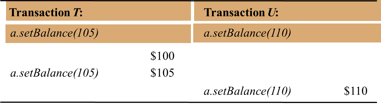
Strict executions of transactions
- The executions of transactions are called strict if the service delays both read and write operations on an object until all transactions that previously wrote that object have either committed or aborted.
- Enforces isolation property.
Tentative versions
- For a server of recoverable objects to participate in transactions, it must be designed so that any updates of objects can be removed when a transactions aborts.
- All of the update operations performed during a transaction are done in tentative versions of objects in volatile memory.
- Each transaction is provided with its own private set of tentative versions of any object that it has altered.
- The tentative versions are transferred to the objects only when a transaction commits, by which time they will also have been recorded in permanent storage.
7.5. Nested transactions
Allowing transactions to be composed of other transactions.
A subtransaction appears atomic to its parent with respect to transaction failures and concurrent access.
Subtransactions at the same level, can run concurrently, but their access to common objects is serialized.
When a subtransaction aborts, the parent transaction can sometimes choose an alternative subtransaction to complete its task.
Main advantages
- Subtransactions at one level (and their descendants) may run concurrently with other subtransactions at the same level in the hierarchy.
- Allow additional concurrency in a transaction
- Subtransactions can commit or abort independently.
The rules of committing nested transactions
- A transaction may commit or abort only after its child transactions have completed.
- When a subtransaction completes, it makes an independent decision either to commit provisionally or to abort. Its decision to abort is final.
- When a parent aborts, all of its subtransactions are aborted.
- When a subtransaction aborts, the parent can decide whether to abort or not.
- If the top-level transaction commits, then all of the subtransactions that have provisionally committed can commit too, provided that none of their ancestors has aborted. The effects of a subtransation are not permanent until the top-level transaction commits.
CORBA Object Transaction Service supports both flat and nested transactions.
Nested transactions are useful in distributed systems because child transactions may be run concurrently in different servers.
Figure 13: Nested transactions
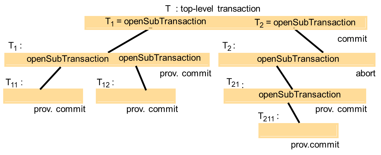
7.6. Locks
Two-phase locking
- Transaction is not allowed any new locks after it has released a lock.
- The first phase of each transaction is a ‘growing phase’, during which new locks are acquired.
- In the second phase, the locks are released (a ‘shrinking phase’).
Strict two-phase locking
- Any locks applied during the progress of a transaction are held until the transaction commits or aborts.
- When a transaction commits, to ensure recoverability, the locks must be held until all the objects it updated have been written to permanent storage.
Concurrency control protocols are designed to cope with conflicts between operations in different transactions on the same object.
Two types of locks are used: read locks and write locks.
All the transactions reading the same object share its read lock – read locks are sometimes called shared locks.
Figure 14: Transactions T and U with exclusive locks
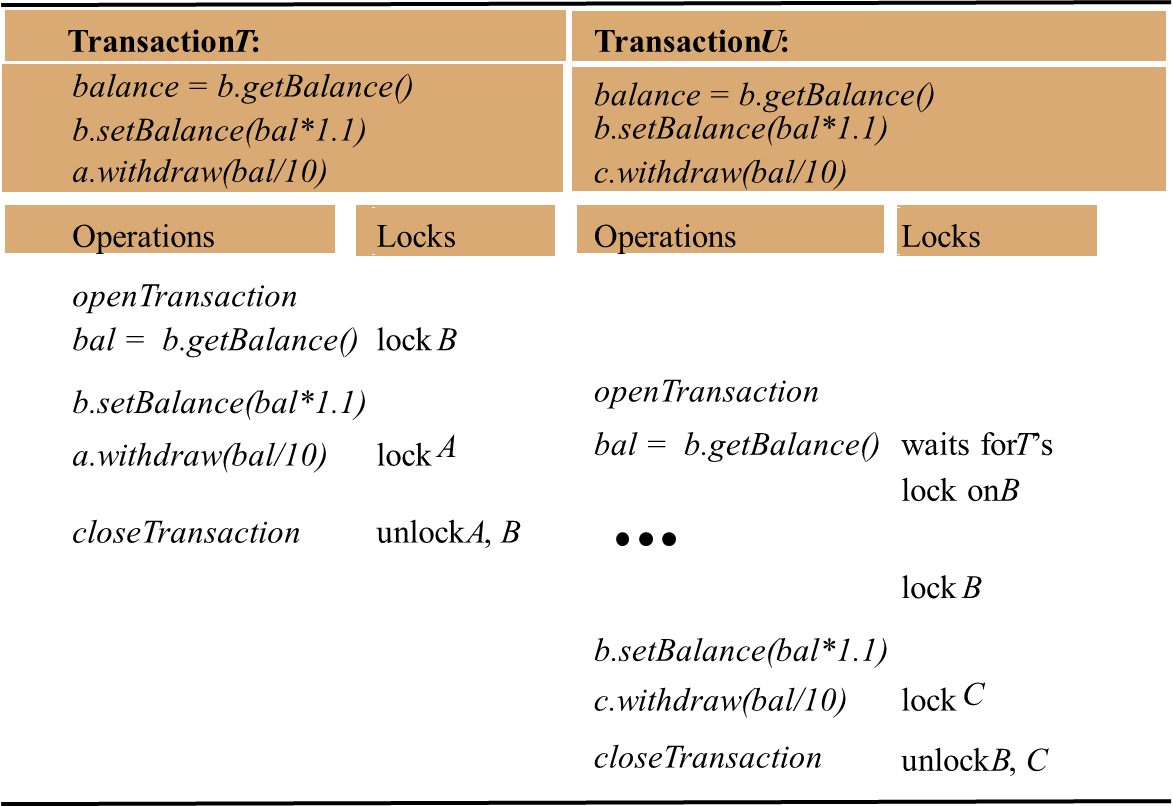
Operation conflict rules
- If a transaction T has already performed a read operation on a particular object, then a concurrent transaction U must not write that object until T commits or aborts.
- If a transaction T has already performed a write operation on a particular object, then a concurrent transaction U must not read or write that object until T commits or aborts.
For the first condition: a request for a write lock on an object is delayed by the presence of a read lock belonging to another transaction.
For the second condition: a request for either a read lock or a write lock on an object is delayed by the presence of a write lock belonging to another transaction.
Inconsistent retrievals:
- Prevented by performing the retrieval transaction before or after the update transaction.
- If it comes first, its read lock delays the update transaction.
- It if comes second, its request for read locks causes it to be delayed until the update transaction has completed.
Figure 15: Lock compatibility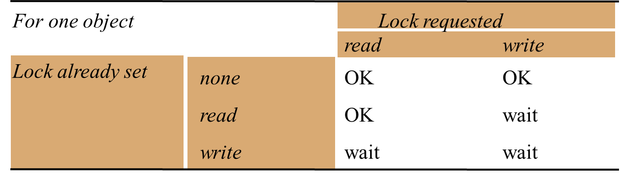
Lost updates
- Prevented by making later transactions delay their reads until the earlier one have been completed.
- Achieved by each transaction setting a read lock when it reads an object and then promoting it to a write lock when it writes the same object – when a subsequent transaction requires a read lock it will be delayed until any current transaction has completed.
- A transaction with a read lock that is shared with other transactions cannot promote its read lock to a write lock.
- This transaction must request a write lock and wait for the other read locks to be released.
Figure 16: Use of locks in strict two-phase locking

Increasing concurrency in locking schemes
- Two-version locking
- Allows one transaction to write tentative versions of objects while other transactions read from the committed versions of the same objects.
- Read operations only wait if another transaction is currently committing the same object.
- Transactions cannot commit their write operations immediately if other uncompleted transactions have read the same objects.
- Must wait until the reading transactions have completed.
- Deadlocks may occur
- Transactions are waiting to commit
- May need to abort some transactions when they are waiting to commit to resolve deadlocks.
- 3 types of locks: read lock, write lock and commit lock.
- i. Read lock
- set before the transaction’s read operation on an object
- Attempt to set will be successful unless the object has a commit lock.
- ii. Write lock
- Set before a transaction’s write operation is performed on an object.
- Attempt to set will be successful unless the object has a write lock or a commit lock
- When the transaction coordinator receives a request to commit a transaction, it attempts to convert all the transaction’s write locks to commit locks.
- If any of the objects have outstanding read locks, the transaction must wait until the other transactions have completed and the locks are released.
Figure 24: Lock compatibility (read, write and commit locks)
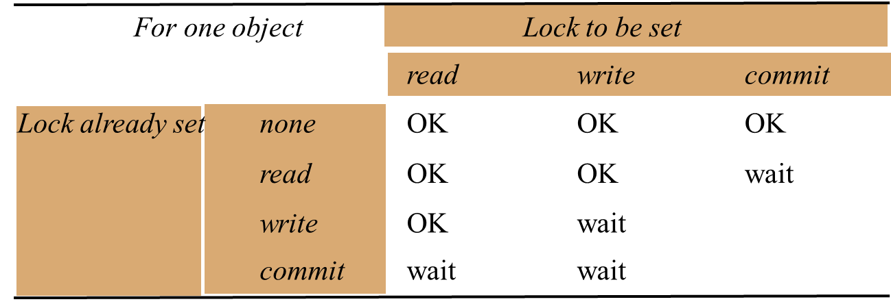
iii. Hierarchic locks
- In some applications, the granularity suitable for one operation is not appropriate for another operation.
- Example:
- Majority of the operations require locking at the granularity of an account.
- But the branchTotal operation require a read lock on all of the accounts.
- To reduce locking overheads, it would be useful to allow locks of mixed granularity to coexist.
- At each level, the setting of a parent lock has the same effect as setting all the equivalent child locks.
- Banking example: branch is parent and accounts are children.
- Also useful in a diary system.
Figure
25: Lock hierarchy for the banking example
Figure 26: Lock hierarchy for a diary

7.7. Flat and nested distributed transactions
Flat transaction
- Client makes requests to more than one server.
- Flat client transaction completes each of its requests before going on to the next one.
- Each transaction accesses servers’ objects sequentially.
- When servers use locking, a transaction can only be waiting for one object at a time.
Nested transaction
- Top-level transaction can open subtransactions, and each subtransaction can open further subtransactions down to any depth of nesting.
- Subtransactions at the same level can run concurrently.
- In the following figure, the four requests (two deposits and two withdraws) can run in parallel and the overall effect can be achieved with better performance than a simple transaction in which the four operations are invoked sequentially.
Figure 28: Distributed transactions
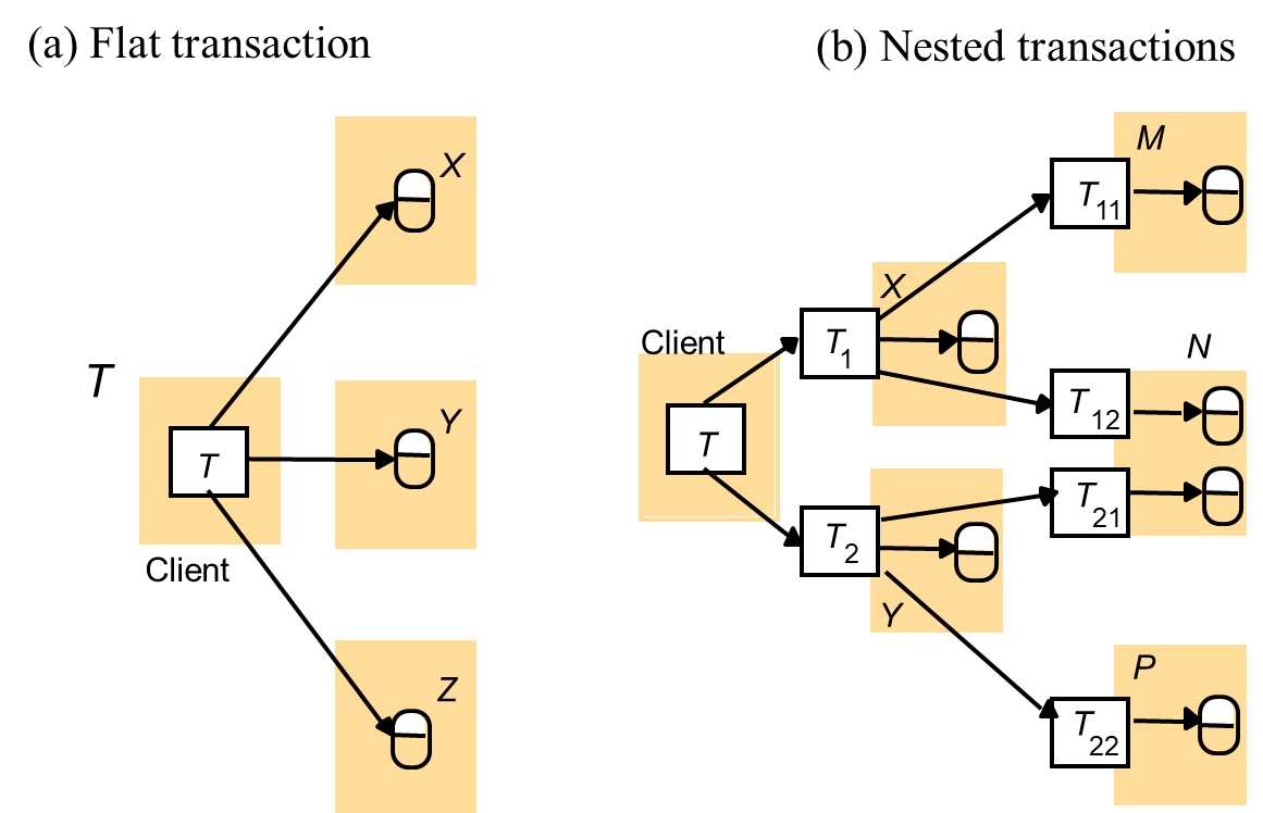
Figure
29: Nested banking transaction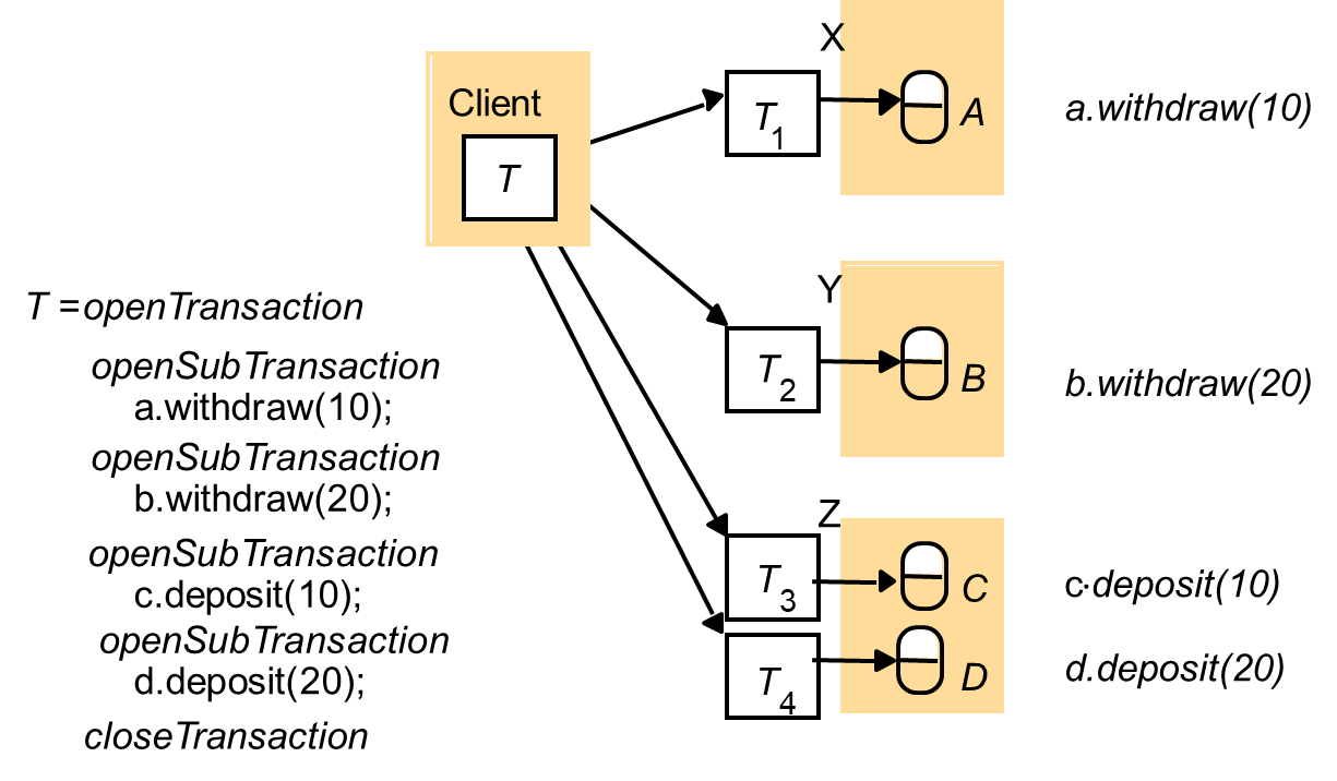
Atomicity property requires that when a distributed transaction comes to an end, either all of its operations are carried out or none of them.
- The client has requested operations at more than one server.
- A transaction comes to an end when the client requests that it be committed or aborted.
One-phase atomic commit protocol
- The coordinator communicate the commit or abort request to all of the participants in the transaction and to keep on repeating the request until all of them have acknowledged that they have carried it out.
- This is inadequate, because it does not allow a server to make a unilateral decision to abort a transaction when the client requests a commit.
- Server might want to abort due to concurrency control (resolve deadlock) or server has crashed and been replaced during the progress of a distributed transaction.
Two-phase commit protocol
- Allow any participant to abort its part of a transaction.
- Atomicity: if one part of a transaction is aborted, then the whole transaction must be aborted.
- First phase:
- Each participant votes for the transaction to be committed or aborted.
- Once a participant has voted to commit a transaction, it is not allowed to abort it.
- So, before a participant votes to commit, it must ensure that it will eventually be able to carry out its part of the commit protocol.
- A participant is said to be in a prepared state for a transaction if it will eventually be able to commit it.
- Each participant saves in permanent storage all of the objects that it has altered in the transaction, together with its status – prepared.
- Second phase:
- Every participant in the transaction carries out the joint decision.
- If any of the participant votes to abort, then the decision must be to abort the transaction.
- If all the participants vote to commit, then the decision is to commit the transaction.
Figure 4: Operations for two-phase commit protocol

Figure 5: The two-phase commit protocol
7.8. Concurrency control in distributed transactions
Locking
- In a distributed transaction, the locks on an object are held locally (in the same server).
- Local lock manager can decide whether to grant a lock or make the requesting transaction wait.
- It cannot release any locks until it knows that the transaction has been committed or aborted at all the servers involved in the transaction.
- As lock managers in different servers set their locks independently of one another, it is possible that different servers may impose different ordering on transactions.
- These different orderings can lead to cyclic dependencies between transactions, giving rise to a distributed deadlock situation.
- When deadlock is detected, a transaction is aborted to resolve the deadlock.
Timestamp ordering concurrency control
- In distributed transactions, each coordinator issue globally unique timestamps.
- A globally unique transaction timestamp is issued to the client by the first coordinator accesses by a transaction.
- The transaction timestamp is passed to the coordinator at each server whose objects perform an operation in the transaction.
- The servers of distributed transactions are jointly responsible for ensuring that they are performed in a serially equivalent manner.
- For reason of efficiency, the timestamp issued by one coordinator is roughly synchronized with those issued by the other coordinators.
- In this case, the ordering of transaction is corresponds to the order in which they are started in real time.
- Timestamp can be kept roughly synchronized by the use of synchronized local physical clock.
Optimistic concurrency control
- A distributed transactions is validated by a collection of independent servers, each of which validates transactions that access its own objects.
- Validation protocol: only one transaction may perform validation and update phases at a time.
- Server might be unable to validate the other transaction until the first one has completed.
- Might lead to commitment deadlock
- Kung and Robinson [1981] proposes parallel validation
- Allow multiple transactions to be in the validation phase at the same time.
- Transactions will not suffer from commitment deadlock.
- If servers perform independent validations, it is possible that different servers in a distributed transaction may serialize the same set of transactions in different orders.
To prevent this – local validation at each server, then global validation is carried out.
Another approach: all of the servers of a particular transaction use the same globally unique transaction number at the start of the validation.
8. Chapter 8: Replication
TOPIC OVERVIEW
- System
model and the role of group communication
- Fault-tolerant services
- The gossip architecture
- Transactions with replicated data
8.1. System model and the role of group communication
System model
- Data in the system consist of a collection of items called objects.
- An ‘object’ could be a file (example: Java object).
- Each such logical object is implemented by a collection of physical copies called replicas.
- Replicas are physical objects, each stored at a single computer, with data and behaviour that are tied to some degree of consistency by the system’s operation.
- The ‘replicas’ of a given object are not necessarily identical, at least not at any particular point in time.
- Some replicas may have received updates that others have not received.
- Assume that an asynchronous system in which processes may fail only by crashing.
- Involves replicas held by distinct replica managers – components that contain the replicas on a given computer and perform operations upon them directly.
- Replica manager applies operations to its replicas recoverably.
- An operation at a replica manager does not leave inconsistent result if it fails part way through.
- A replica manager applies operations to its replicas atomically.
- The state of the replicas is a deterministic function of their initial states and the sequence of operations that it applies to them.
- The set of replica managers may be static or dynamic.
- In a dynamic system
- New replica managers may appear.
- Replica managers may crash, then they are then deemed to have left the system (may be replaced).
- In a static system
- Replica managers do not crash.
- But they may cease operating for an indefinite period.
- A collection of replica managers provides a service to clients.
- Each client’s request are first handled by a component called a front end.
- Front end:
- to communicate by message passing with one or more of the replica managers.
- Making replication transparent.
Figure 1: A basic architectural model for the management of replicated data
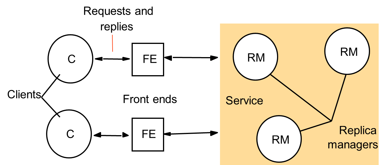
Five phases are involved in the performance of a single request upon the replicated objects
- Requests:
- The front end issues the request to one or more replica managers.
- Coordination:
- The replica managers coordinate in preparation for executing the request consistently.
- They decide on the ordering of this request relative to others.
- Execution
- The replica managers execute the request – perhaps tentatively: they can undo its effect later.
- Agreement
- The replica managers reach consensus on the effect of the request – if any – that will be committed.
- Response
- One or more replica managers responds to the front end.
- The front end pass back the response to the client.
The role of group communication
- Requirement for dynamic membership where processes join and leave the group as the system executes.
- Users may add or withdraw a replica manager, or a replica manager may crash and thus need to be withdrawn from the system’s operation.
- Fault-tolerant system – systems that can adapt as processes join, leave and crash – require more advanced features in failure detection and notification of membership changes.
- Group views
- List of the current group members, identified by their unique process identifiers.
- The list is ordered
- Example: according to the sequence in which the members joined the group.
- New group view is generated each time that a process is added or excluded.
- Process is suspended
- Group membership service exclude it.
- The process is not crashed.
- Might be communication failure -> process unreachable but it continues to execute normally.
- Effect of exclusion:
- No messages will be delivered to that process
- If that process becomes connected again, any messages it attempts to send will not be delivered to the group members.
- The process have to re-join the group (obtain new identifier), or abort its operation.
- However, false suspicion may reduce the group’s effectiveness.
- Design challenge
- Ensure that a system based on group communication does not behave incorrectly if a process is falsely suspected.
For network partitions, group management differ in whether they are primary-partition or partitionable.
Primary-partition
- The management service allows at most one subgroup (a majority) to survive a partition
- The remaining processes are informed that they should suspend operations.
- Appropriate in the case where the processes manage important data and the costs of inconsistencies between two or more subgroups is high.
Partitionable
- Acceptable for two or more subgroups to continue to operate
- Example:
- An application in which users hold an audio or video conference to discuss some issues.
- Maybe acceptable for two or more subgroups of users to continue their discussion independently despite a partition.
- They can merge their results when the partition heals and the subgroups are connected again.
View delivery
- For each group g the group management service delivers to any member process p g a series of views vo(g), v1(g), v2(g), etc.
- For example: a series of views could be vo(g) = (p), v1(g) = (p, p’) and v2(g) = (p) – p joins an empty group, then p’ joins the group, then p’ leaves it.
- Although several membership changes may occur concurrently, the system imposes an order on the sequence of views given to each process.
- Basic requirement for view delivery
- Order: if a process p delivers view v(g) and then view v’(g), then no other process q ≠ p delivers v’(g) before v(g).
- Integrity: if process p delivers view v(g), then p \( \in \) v(g).
- Non-triviality: If process q joins a group and is or becomes indefinitely reachable from process p ≠ q, then eventually q is always in the views that p delivers. Similarly, if the group partitions and remains partitioned, then eventually the views delivered in any one partition will exclude any processes in another partition.
View-synchronous group communication
- For simplicity, assume partitions may not occur.
- Makes guarantees additional to those above about the delivery ordering of view notifications with respect to the delivery of multicast messages.
- The guarantees:
- Agreement: Correct processes deliver the same sequence of views (starting from the view in which they join the group) and the same set of messages in any given view. That is, if a correct process delivers message m in view v(g), then all other correct processes that deliver m also do so in the view v(g).
- Integrity: If a process p delivers message m, then it will not deliver m again.
- Validity: Correct process always deliver the messages that they send. Let p be any correct process that delivers message m in view v(g). If some process q \( \in \) v(g) does not deliver m in view v(g), then the next view v’(g) that p delivers has q \( \notin \) v’(g).
Figure 2: View-synchronous group communication

8.2. Fault-tolerant services
Introduction:
- Each replica manager is assumed to behave according to a specification of the semantics of the objects it manages, when they have not crashed.
- Anomalies can arise when there are several replica managers.
- Example:
- Replication system, where a pair of replica managers at computers A and B each maintain replicas of two bank accounts, x and y.
- Clients read and update the accounts at their local replica manager but try another replica manager if the local one fails.
- Replica managers propagate updates to one another in the background after responding to the clients.
- Both accounts initially have a balance of $0.
- Client 1 updates the balance of x at its local replica manager B to be $1 and then attempts to update y’s balance to be $2, but discovers that B has failed.
- Client 1 therefore applies the update at A instead.
- Now client 2 reads the balances at its local replica manager A.
- It finds first that y has $2 and then that x has $0 – the update to bank account x from B has not arrived, since B failed.
- Client 2 should have read a balance of $1 for x, given that it read the balance of $2 for y, since y’s balance was update after that of x.
Client 1: Client 2:
setBalanceB(x, 1)
setBalanceA(y, 2)
- There are various correctness criteria for replicated objects.
- A replicated shared object service is said to be linearizable if for any execution there is some interleaving of the series of operations issued by all the clients that satisfies the following two criteria:
- The interleaved sequence of operations meets the specification of a (single) correct copy of the objects.
- The order of operations in the interleaving is consistent with the real times at which the operations occurred in the actual execution.
- The real-time requirement in linearizability captures our notion that clients should receive up-to-date information.
- But, the presence of real time raises the issue of linearizability’s practically – we cannot synchronize clocks to the required degree of accuracy.
ii. Sequential consistency
- It just captures an essential requirement concerning the order in which requests are processed without appealing to real time.
- Criteria:
- The interleaved sequence of operations meets the specification of a (single) correct copy of the objects.
- The order of operations in the interleaving is consistent with the program order in which each individual client executed them.
- The interleaving of operations can shuffle the sequence of operations from a set of clients in any order, as long as each client’s order is not violated and the result of each operation is consistent, in terms of objects’ specification, with the operations preceded it.
- This is similar to shuffling together several packs of cards so that they are intermingled in such a way as to preserve the original order of each pack.
- Every linearizable service is also sequentially consistent, since real-time order reflects each client’s program order.
- But the converse does not hold.
- Example:
- The real-time criteria for linearizablity is not satisfied, since getBalanceA(x) -> 0 occurs later than setBalanceB(x, 1); but the following interleaving satisfies both criteria for sequential consistency: getBalanceA(y) -> 0, getBalanceA(x) -> 0, setBalanceB(x, 1), setBalanceA(y, 2).
Client A: Client 2:
setBalanceB(x, 1)
getBalanceA(y) -> 0
getBalanceA(x) -> 0
setBalanceA(y, 2)
iii. Passive (primary-backup) replication
- There is at any one time a single primary replica manager and one or more secondary replica managers – ‘backups’ or ‘slaves’.
- Front ends communicate only with the primary replica manager to obtain the service.
- The primary replica manager executes the operations and sends copies of the updated data to the backups.
- If the primary fails, one of the backups is promoted to act as the primary.
- Sequence of events when a client requests an operation to be performed:
- Request: The front end issues the request, containing a unique identifier, to the primary replica manager.
- Coordination: The primary takes each request atomically, in the order in which it receives it. It checks the unique identifier, in case it has already executed the request, and if so it simply resends the response.
- Execution: The primary executes the request and stores the response.
- Agreement: If the request is an update, then the primary sends the updated state, the response and the unique identifier to all the backups. The backups send an acknowledgement.
- Response: The primary responds to the front end, which hands the response back to the client.
- The system implements linearizability if the primary is correct, since the primary sequences all the operations upon the shared objects.
- If the primary fails, then the system retains linearizability if a single backup becomes the new primary, and if
- The primary is replaced by a unique backup (if two clients begin using two backups, then the system could perform incorrectly)
- The replica managers that survive agree on which operations had been performed at the point when the replacement primary takes over.
iv. Active replication
- The replica managers are state machines that play equivalent roles and are organized as a group.
- Front ends multicast their requests to the group of replica managers and all the replica managers process the request independently but identically and reply.
- If any replica manager crashes, this need have no impact upon the performance of the service, since the remaining replica managers continue to respond in the normal way.
- The sequence of events when a client requests an operation to be performed:
- Request:
- The front end attaches a unique identifier to the request and multicasts it to the group of replica managers, using a totally ordered, reliable multicast primitive.
- The front end is assumed to fail by crashing at worst.
- It does not issue the next request until it has received a response.
- Coordination: The group communication system delivers the request to every correct replica manager in the same (total) order.
- Execution:
- Every replica manager executes the request.
- Since they are state machine and since requests are delivered in the same total order, correct replica managers all process the request identically.
- The response contains the client’s unique request identifier.
- Agreement: No agreement phase is needed
- Response:
- Each replica manager sends its response to the front end.
- The front end might passes the first response to arrive back to the client and discards the rest.
- The system achieves sequential consistency.
- Each front end’s requests are served in FIFO order, which is the same as ‘program order’.
- It is not linearizability → The total order in which the replica managers process request is not necessarily the same as the real-time order in which the clients made their requests
Figure 4: Active replication
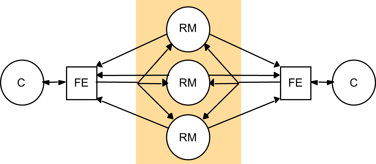
8.3. The gossip architecture
The emphasis is on giving client access to the service – with reasonable response times – for as much of the time as possible, even if some results do not conform to sequential consistency.
The gossip architecture
- Proposed by Ladin et al. [1992]
- Framework for implementing highly available services by replicating data close to the points where groups of clients need it.
- The replica managers exchange ‘gossip’ messages periodically in order to convey the updates they have each received from clients.
- It maybe used to create a highly available electronic bulletin board or diary service.
- Two basic operations:
- Queries – read only operations
- Updates – modify but do not read the state
Figure 5: Query and update operations in a gossip service
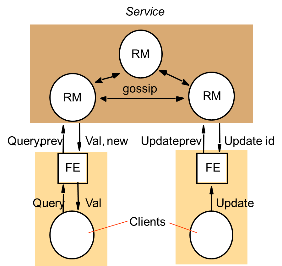
- Front ends send queries and updates to any replica manager they choose, provided it is available and can provide reasonable response times.
- Two guarantees:
- Each client obtains a consistent service over time
- Relaxed consistency between replicas
- To support relaxed consistency, the gossip architecture supports causal update ordering.
- Example:
- Consider an electronic bulletin board application, in which a client program executes on the user’s computer and communicates with a local replica manager.
- The client sends the user’s posting to the local replica manager and the replica manager sends new postings in gossip messages to other replica managers.
- Readers of bulletin boards experience slightly out-of-date lists of posted items, but this does not usually matter.
- Causal ordering could be used for posting items.
- General postings could appear in different orders at different replica managers but that, for example, a posting whose subject is ‘Re: oranges’ will always be posted after the message about ‘oranges’ to which it refers.
- Forced ordering could be used for adding a new subscriber to a bulletin board.
- Outline of how a gossip service processes queries and update operations is as follows:
- Request:
- The front end normally sends requests to only a single replica manager at a time.
- A front end will communicate with a different replica manager when the one it normally uses fails, becomes unreachable or heavily loaded.
- Update response:
- If the request is an update, then the replica manager replies as soon as it has received the update.
- Coordination
- The replica manager that receives a request does not process it until it can apply the request according to the required ordering constraints.
- This may involve receiving updates from other replica managers, in gossip messages.
- Execution
- Query response
- If the request is a query, then the replica manager replies at this point.
- Agreement
- The replica managers update one another by exchanging gossip messages, which contain the most recent updates they have received.
- Gossip messages may be exchanged only occasionally, after several updates have been collected, or when a replica manger finds out that it is missing an update sent to one of its peers that it needs to process a request.
The front end’s version timestamp
- In order to control the ordering of operation processing, each front end keeps a vector timestamp that reflects the version of the latest data values accessed by the front end.
- This timestamp, denoted by prev.
- The front end sends it in every request message to a replica manager, together with a description of the query or update operation itself.
- When a replica manager returns a value as a result of a query operation, it supplies a new vector timestamp (new).
- An update operation returns a vector timestamp (UpdateID) that is unique to the update.
- Each returned timestamp is merged with the front end’s previous timestamp to record the version of the replicated data that has been observed by the client.
- Clients exchange data by accessing the same gossip service and by communicating directly to one another.
Figure 6: Front ends propagate their timestamps
whenever clients communicate directly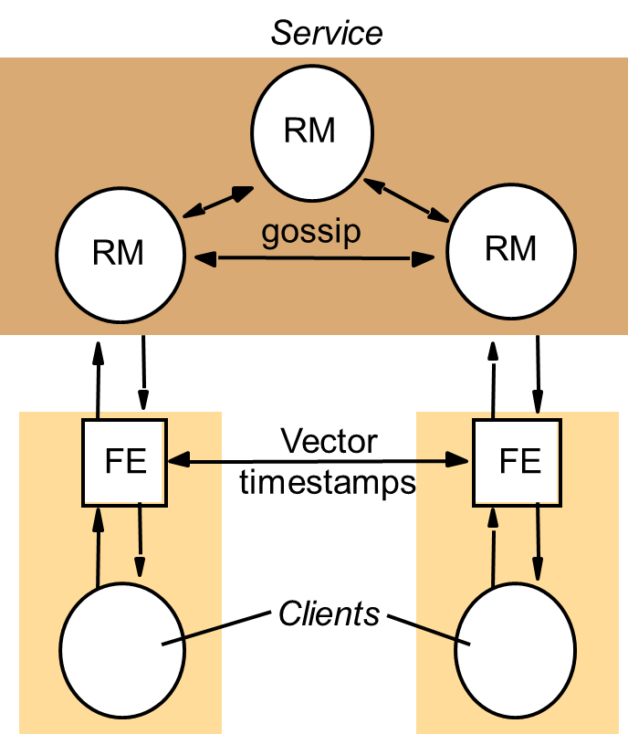
Replica manager state
- Value:
- Value of the application state as maintained by the replica manager.
- Replica manager is a state machine, which begins with a specified initial value and is thereafter solely the result of applying update operations to that state.
- Value timestamp:
- Vector timestamp that represents the updates that are reflected in the value.
- Contain one entry for every replica manager.
- Updated whenever an update operation is applied to the value.
- Update log:
- All update operations are recorded in this log as soon as they are received.
- Replica manager keeps updates in a log because:
- The replica manager cannot yet apply the update because it is not yet stable. Stable update – the one that may be applied consistently with its ordering guarantees.
- Even though the update has become stable and has been applied to the value, the replica manager has not received confirmation that this update has been received at all other replica managers.
- In the meantime, it propagates the update in gossip messages.
- Replica timestamp:
- Vector timestamp that represents those updates that have been accepted by the replica manager – that is, placed in the manager’s log.
- Differs from the value timestamp in general, because not all updates in the log are stable.
- Executed operation table:
- The same update may arrive at a given replica manager from a front end and in gossip messages from other replica managers.
- To prevent an update being applied twice, the ‘executed operation’ table containing the unique front-end-supplied identifiers of updates that have been applied to the value.
- The replica managers check this table before adding an update to the log.
- Timestamp table:
- Vector timestamp for each other replica manager, filled with timestamps that arrive from them in gossip messages.
- Replica managers use the table to establish when an update has been applied at all replica managers.
Figure 7: A gossip replica manager,
showing its main state components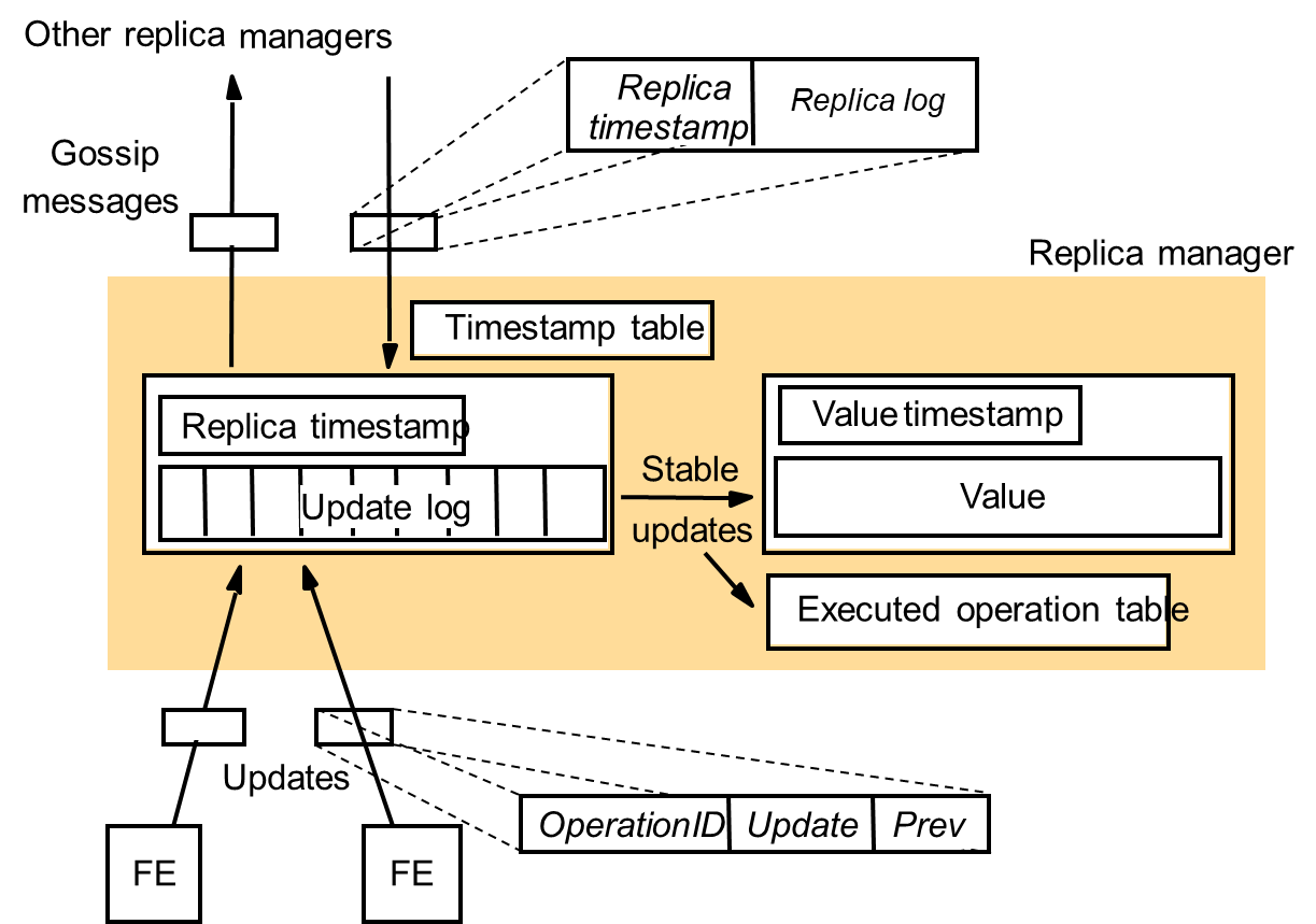
Discussion of the gossip architecture
- Aimed at achieving high availability for services.
- Ensures that clients can continue to obtain a service even when they are partitioned from the rest of the network, as long as at least one replica manager continues to function in their partition.
- For objects such as bank accounts, where sequential consistency is required, it is not suitable as it enforcing relaxed consistency.
- Fault tolerant system should be much better.
- Its lazy approach to update propagation makes it inappropriate for updating replicas in near-real time.
- Multicast-based system would be more appropriate.
- Scalability issue
- As the number of replica managers grows, the number of gossip messages and the size of the timestamps used grow.
8.4. Transactions with replicated data
Introduction
- From a client’s view point, a transaction on replicated objects should appear the same as one with non-replicated objects.
- In a non-replicated system, transaction appear to be performed one at a time in some order.
- This is achieved by ensuring a serially equivalent interleaving of clients’ transactions.
- The effect of transactions performed by clients on replicated objects should be the same as if they had been performed one at a time on a single set of objects.
- This property is called one-copy serialization.
Architectures for replicated transactions
- Client request to replica managers issue
- A front end may either multicast client requests to groups of replica managers or send each request to a single replica manager, which is then responsible for processing the request and responding to the client.
- Primary copy approach – all front ends communicate with a distinguished ‘primary’ replica manager to perform an operation, and that replica manager keeps the backups up-to-date.
- Front ends may communicate with any replica manager to perform an operation – but coordination between replica manager is consequently more complex.
- Number of replica managers required for the successful completion of an operation issue
- Different replication schemes have different rules as to how many of the replica managers in a group are required for the successful completion of an operation.
- Example: read-one/write-all scheme – a read request can be performed by a single replica manager, whereas a write request must be performed by all the replica managers in the group.
- Quorum consensus schemes – to reduce the number of replica managers that must perform update operations, but at the expense of increasing number of replica managers required to perform read-only operations
- Another issue is whether the replica manager contacted by a front end should defer the forwarding of update requests to other replica managers in the group until after a transaction commits - Lazy approach to update propagation
- Eager approach – replica managers should forward each update request to all the necessary replica managers within the transaction and before it commits.
Figure 9: Transactions on replicated data
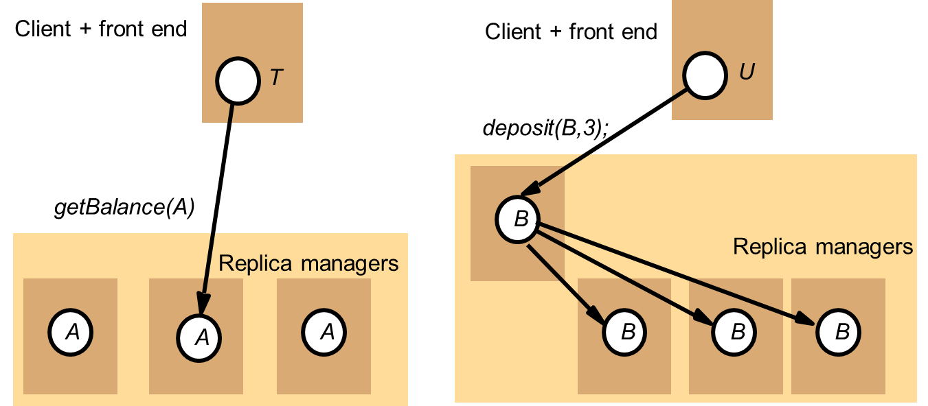
Quorum consensus methods
- One way of preventing transactions in different partitions from producing inconsistent results is to make a rule that operations can be carried out within only one of the partitions.
- A quorum is a subgroup of replica managers whose size gives it the right to carry out operations.
- Gifford [1979] developed a file replication scheme in which a number of ‘votes’ are assigned to each physical copy at a replica manager of a single logical file.
- A vote can be regarded as a weighting related to the desirability of using a particular copy.
- Each read operation must first obtain a read quorum of R votes before it can proceed to read from any up-to-date copy, and each write operation must obtain a write quorum of W votes before it can proceed with an update operation.
- R and W are set for a group of replica managers such that
- W > half the total votes
- R + W > total number of votes for the group
- This ensures that any pair consisting of a read quorum and a write quorum or two write quorum must contain common copies.
- To perform read operation
- A read quorum is collected by making sufficient version number enquiries to find a set of copies, the sum of whose votes is not less than R.
- Not all of these copies need be up-to-date.
- Since each read quorum overlaps with every write quorum, every read quorum is certain to include at least one current copy.
- The read operation may be applied to any up-to-date copy.
- To perform write operation
- A write quorum is collected by making sufficient version number enquiries to find a set of replica managers with up-to-date copies, the sum of whose votes is not less than W.
- If there are insufficient up-to-date copies, then a non-current file is replaced with a copy of the current file, to enable the quorum to be established.
- The updates specified in the write operation are then applied by each replica manager in the write quorum, the version number is incremented and completion of the write is reported to the client.
- The files at the remaining available replica managers are then updated by performing the write operation as a background task.
- Any replica manager whose copy of the file has an older version number than the one used by the write quorum updates it by replacing the entire file with a copy obtained from a replica manager that is up-to-date.
- Configurability of groups of replica managers
- An important property of the weighted voting algorithm is that groups of replica managers can be configured to provide different performance or reliability characteristics.
- Once the general reliability and performance of a group of replica managers is established by its voting configuration, the reliability and performance of write operations maybe increased by decreasing W and similarly for reads by decreasing R.
- An example from Gifford
- Gifford gives 3 examples showing the range of properties that can be achieved by allocating weights to the various replica managers in a group and assigning R and W appropriately.
- The blocking probabilities give an indication of the probability that a quorum cannot be obtained when a read or write request is made.
- They are calculated assuming that there is a 0.01 probability that any single replica manager will be unavailable at the time of a request.
- Example 1:
- Configured for a file with a high read-to-write ratio in an application with several weak representatives and a single replica manager.
- Replication is used to enhance the performance of the system, not the reliability.
- There is one replica manager on the local network that can be accessed in 75 milliseconds.
- 2 clients have chosen to make weak representatives on their local disks, which they can access in 65 milliseconds, resulting in lower latency and less network traffic.
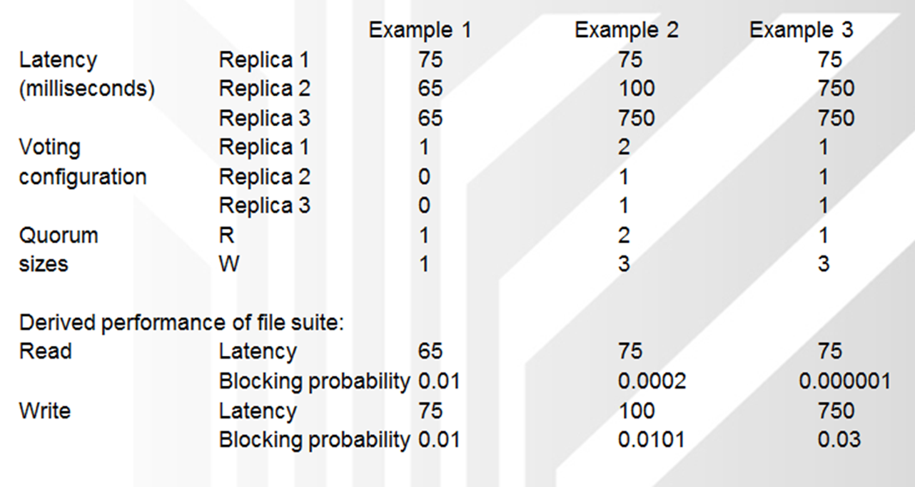
- Example 2:
- Configured for a file with a moderate read-to-write ratio, which is accessed primarily from one local network.
- The replica manager on the local network is assigned two votes and the replica managers on the remote networks are assigned one vote each.
- Reads can be satisfied from the local replica manager, but writes must access the local replica manager and one remote replica manager.
- The file will remain available in read-only mode if the local replica manager fails.
- Clients should create local weak representatives for lower read latency.
- Example 3:
- Configured for a file with a very high read-to-write ratio.
- Clients can read from any replica manager, and the probability that the file will be unavailable is small.
- Updates must be applied to all copies.
- Once again, clients could create weak representatives on their local machines for lower read latency.
- The main disadvantage of quorum consensus is that the performance of read operations is degraded by the need to collect a read quorum from R replica managers.
9. Chapter 9: Peer-to-peer networks
TOPIC OVERVIEW
- Types of peer-to-peer networks
- Routing overlays
- Challenges in peer-to-peer
9.1. Introduction
Types of peer-to-peer networks
- Directory-based (e.g., original Napster design)
- Unstructured (e.g., Gnutella, Kazaa, BitTorrent)
- Structured (e.g., distributed hash tables)
Routing overlays
- Overlay networks
- Connect most P2P systems
Challenges in peer-to-peer
- Legal issues, free riding, fast response to queries, peers coming and going over time, reliability, security,
9.2. Routing Overlays
Alternative routing strategies
- No application-level processing at the overlay nodes
- Packet-delivery service with new routing strategies
Incremental enhancements to IP
- IPv6
- Multicast
- Mobility
- Security
Revisiting where a function belongs
- End-system multicast: multicast distribution by end hosts
Customized path selection
- Resilient Overlay Networks: robust packet delivery
9.3. Application architectures
Client-server
architecture 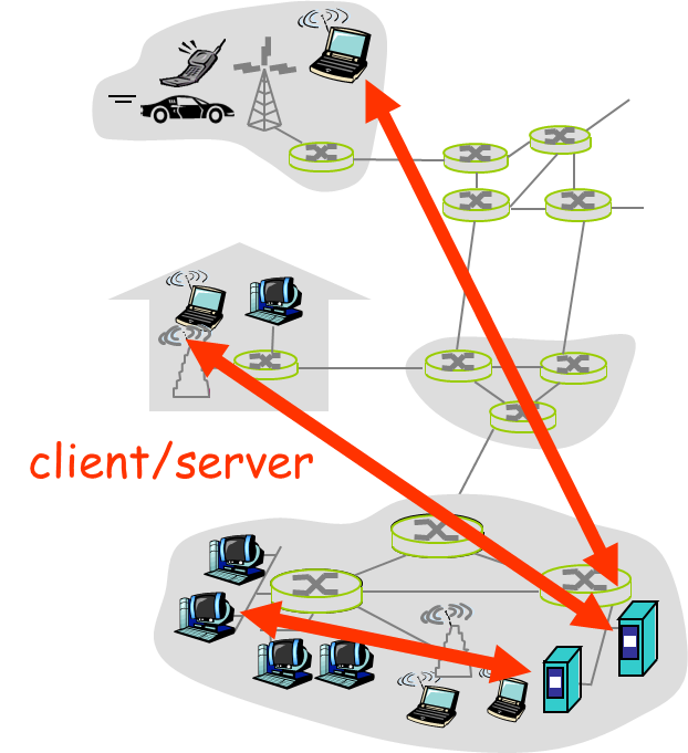
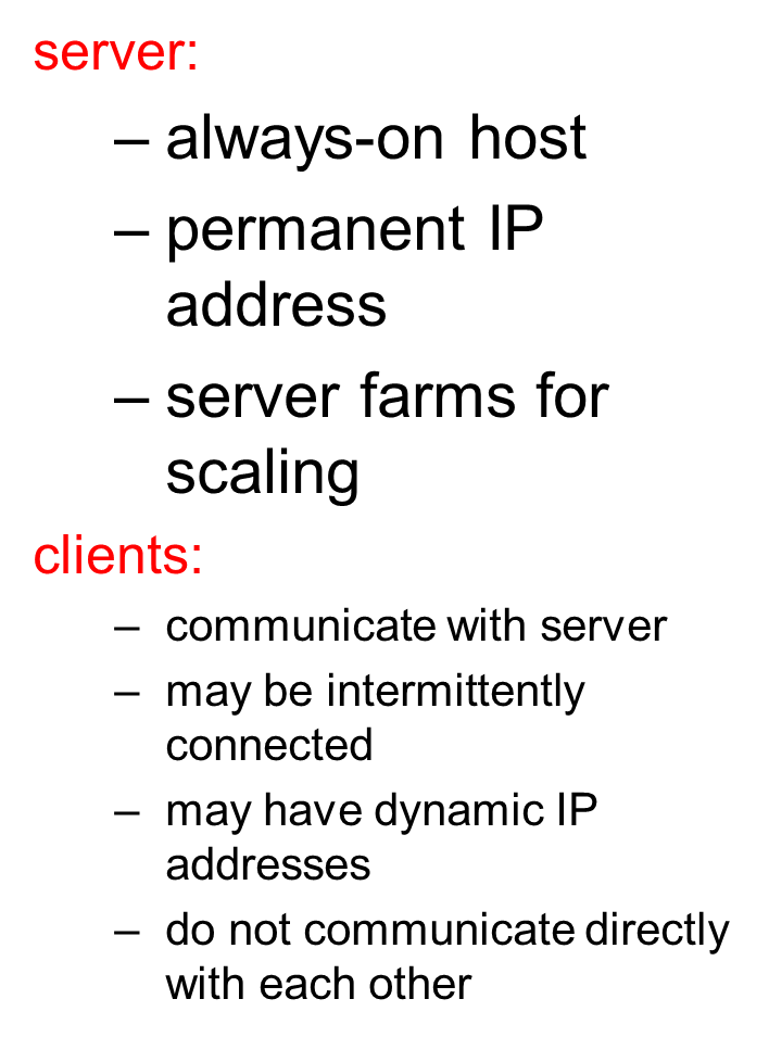
Pure
P2P architecture
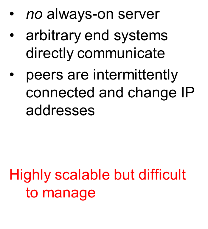
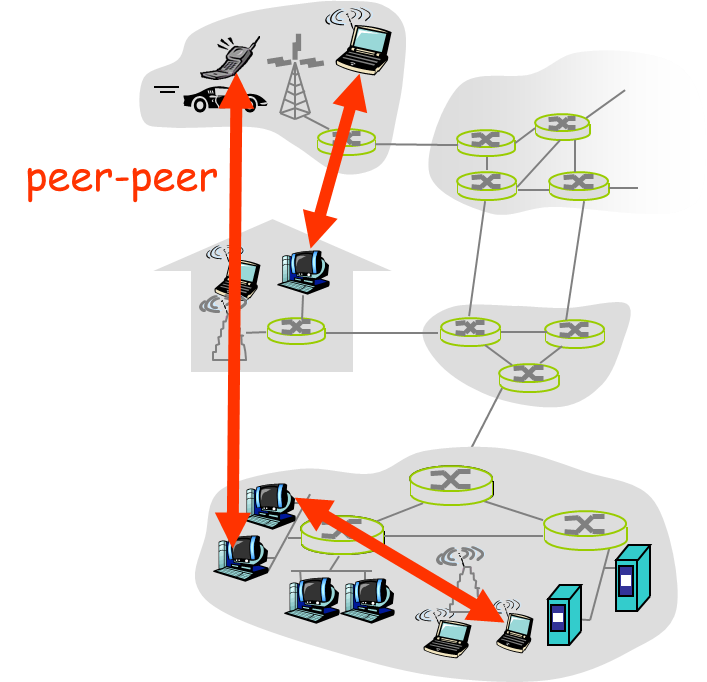
Hybrid
of client-server and P2P
Skype
- voice-over-IP P2P application
- centralized server: finding address of remote party:
- client-client connection: direct (not through server)
Instant messaging
- chatting between two users is P2P
- centralized service: client presence detection/location
- user registers its IP address with central server when it comes online
- user contacts central server to find IP addresses of buddies
Process: program running within a host.
- within same host, two processes communicate using inter-process communication (defined by OS).
- processes in different hosts communicate by exchanging messages
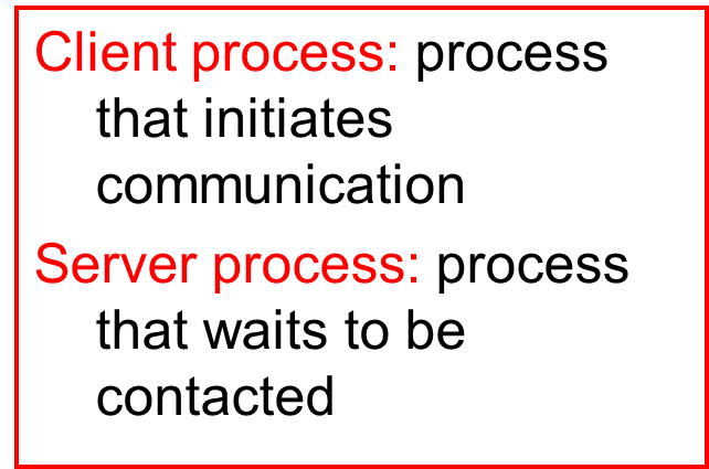
- Note: applications with P2P architectures have client processes & server processes
9.4. Pure P2P architecture
- no always-on server
- arbitrary end systems directly communicate
- peers are intermittently connected and change IP addresses
- Three topics:
- File distribution
- Searching for information
- Case Study: Skype

File
Distribution: Server-Client vs P2P
Question : How much time to distribute file from one server to N peers?
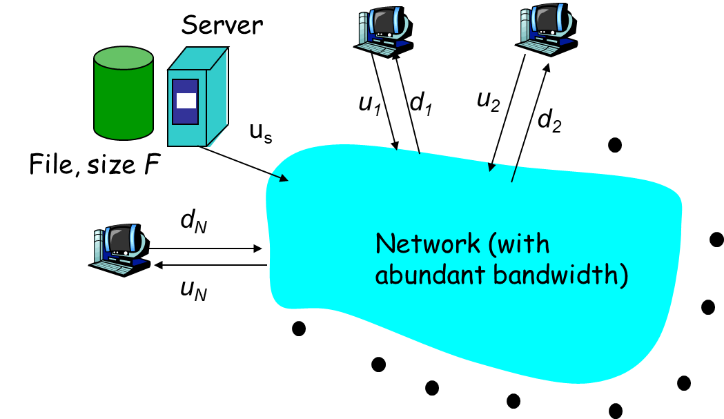
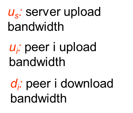
- server sequentially sends N copies:
- NF/us time
- client i takes F/di time to download
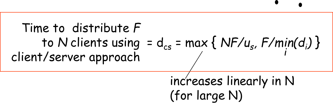
File distribution time: P2P
- server must send one copy: F/us time
- client i takes F/di time to download
- NF bits must be downloaded (aggregate)
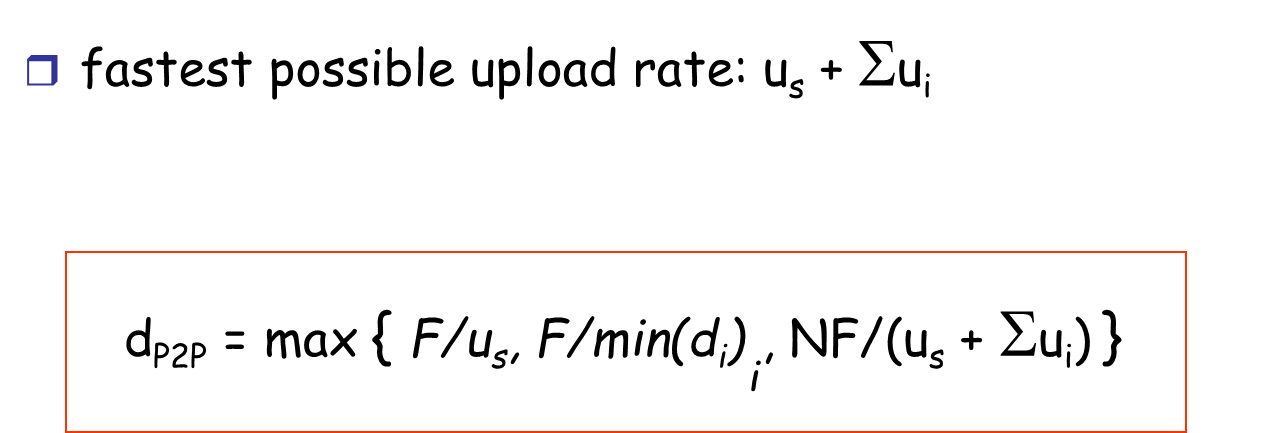
Server-client vs. P2P: example
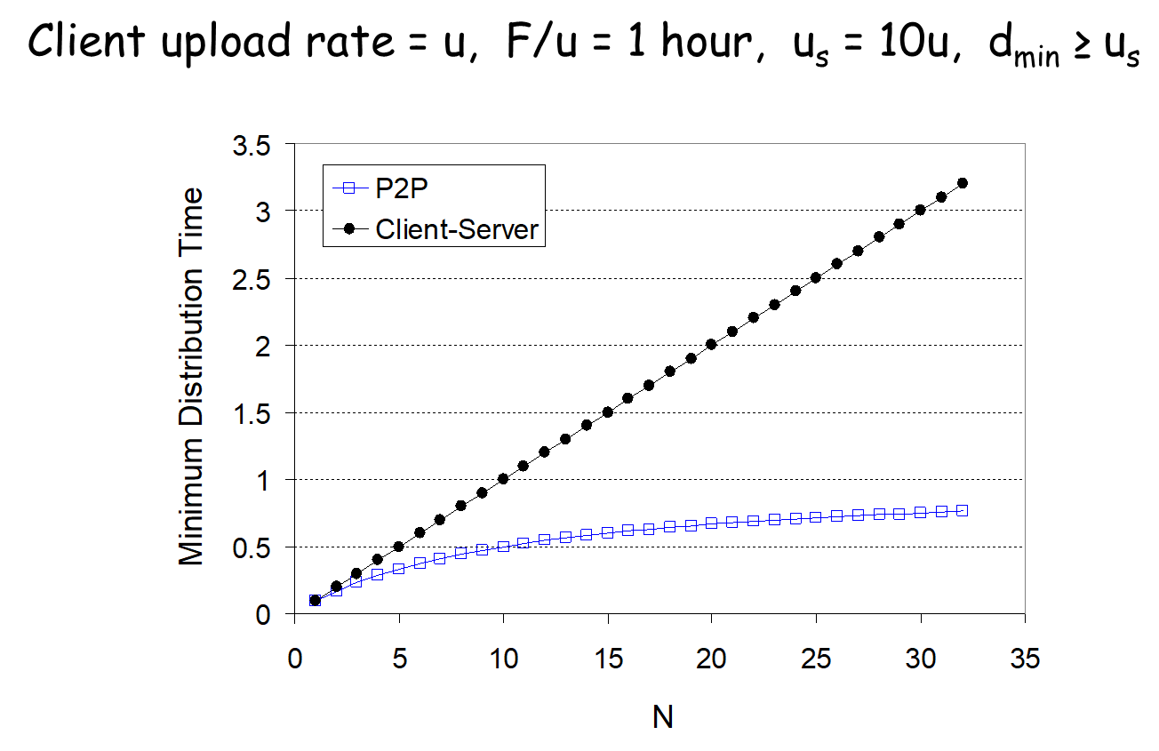
9.5. P2P: searching for information
Index in P2P system: maps information to peer location
(location = IP address & port number)
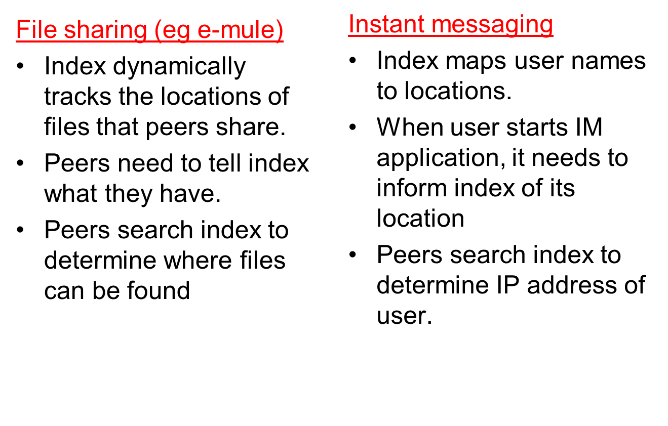
Peer-to-Peer Networks: Napster

Napster history: the rise
- January 1999: Napster version 1.0
- May 1999: company founded
- September 1999: first lawsuits
- 2000: 80 million users
Napster history: the fall
- Mid 2001: out of business due to lawsuits
- Mid 2001: dozens of P2P alternatives that were harder to touch, though these have gradually been constrained
- 2003: growth of pay services like iTunes
Napster history: the resurrection
- 2003: Napster reconstituted as a pay service
- 2006: still lots of file sharing going on
Napster Technology: Directory Service
![]()
- User installing the software
- Download the client program
- Register name, password, local directory, etc.
- Client contacts Napster (via TCP)
- Provides a list of music files it will share
- … and Napster’s central server updates the directory
- Client searches on a title or performer
- Napster identifies online clients with the file
- … and provides IP addresses
- Client requests the file from the chosen supplier
- Supplier transmits the file to the client
- Both client and supplier report status to Napster
Napster Technology: Properties
- Server’s directory continually updated
- Always know what music is currently available
- Point of vulnerability for legal action
- Peer-to-peer file transfer
- No load on the server
- Plausible deniability for legal action (but not enough)
- Proprietary protocol
- Login, search, upload, download, and status operations
- No security: cleartext passwords and other vulnerability
- Bandwidth issues
- Suppliers ranked by apparent bandwidth & response time
Napster: Limitations of Central Directory
- Single point of failure
- Performance bottleneck
- Copyright infringement
- So, later P2P systems were more distributed
P2P:
centralized index
original “Napster” design
- when peer connects, it informs central
server:– IP address
– content - Alice queries for “Hey Jude”
- Alice requests file from Bob
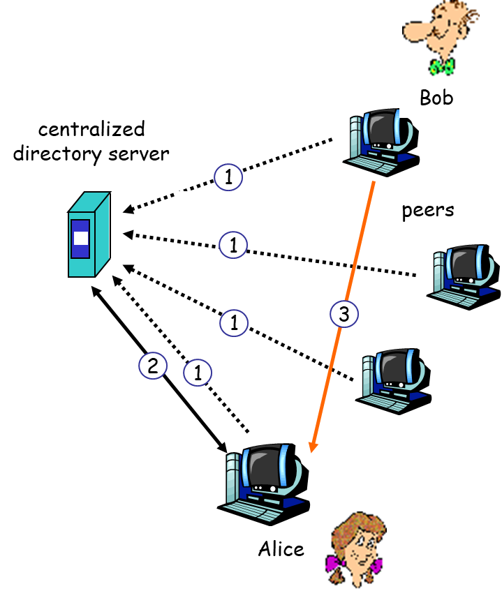
- single point of failure
- performance bottleneck
- copyright infringement: “target” of lawsuit is obvious
9.6. Peer-to-Peer Networks: Gnutella
Peer-to-Peer Networks: Gnutella
- Gnutella history
- 2000: J. Frankel & T. Pepper released Gnutella
- Soon after: many other clients (e.g., Morpheus, Limewire, Bearshare)
- 2001: protocol enhancements, e.g., “ultrapeers”
- Query flooding
- Join: contact a few nodes to become neighbors
- Publish: no need!
- Search: ask neighbors, who ask their neighbors
- Fetch: get file directly from another node

Gnutella: Query Flooding
- Fully distributed
- No central server
- Public domain protocol
- Many Gnutella clients implementing protocol
- Overlay network: graph
- Edge between peer X and Y if there’s a TCP connection
- All active peers and edges is overlay net
- Given peer will typically be connected with < 10 overlay neighbors
Gnutella:
Protocol
- Query message sent over existing TCP connections
- Peers forward Query message
- QueryHit sent over reverse path

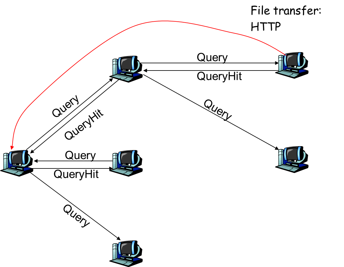
Gnutella: Peer Joining
- Joining peer X must find some other peer in Gnutella network: use list of candidate peers
- X sequentially attempts to make TCP with peers on list until connection setup with Y
- X sends Ping message to Y; Y forwards Ping message.
- All peers receiving Ping message respond with Pong message
- X receives many Pong messages. It can then setup additional TCP connections
Gnutella: Pros and Cons
- Advantages
- Fully decentralized
- Search cost distributed
- Processing per node permits powerful search semantics
- Disadvantages
- Search scope may be quite large
- Search time may be quite long
- High overhead and nodes come and go often
9.7. Hierarchical Overlay
- between centralized index, query flooding approaches
- each peer is either a super node or assigned to a super node
- TCP connection between peer and its super node.
- TCP connections between some pairs of super nodes.
- Super node tracks content in its children

9.8. P2P Case study: Skype
P2P Case study: Skype
- inherently P2P: pairs of users communicate.
- proprietary application-layer protocol (inferred via reverse engineering)
- hierarchical overlay with SNs
- Index maps usernames to IP addresses; distributed over SNs
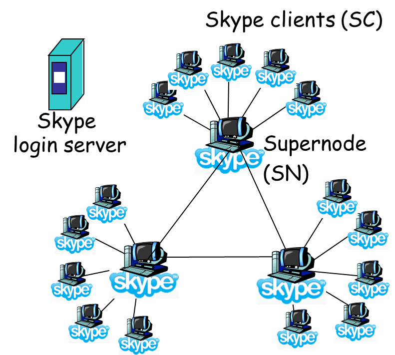
Peers
as relays
- Problem when both Alice and Bob are behind “NATs”.
- NAT prevents an outside peer from initiating a call to insider peer
- Solution:
- Using Alice’s and Bob’s SNs, Relay is chosen
- Each peer initiates session with relay.
- Peers can now communicate through NATs via relay
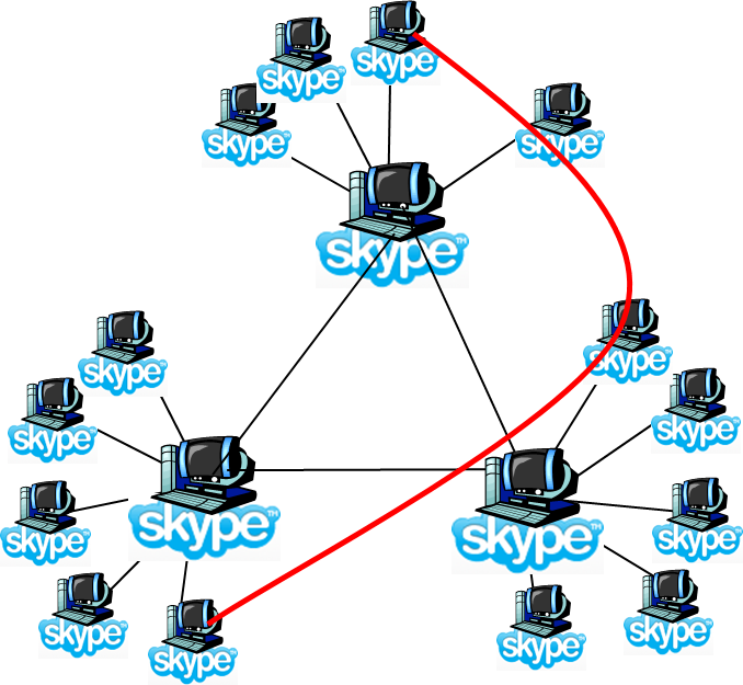
9.9. Peer-to-Peer Networks: KaAzA
Peer-to-Peer Networks: KaAzA

KaZaA history
- 2001: created by Dutch company (Kazaa BV)
- Single network called FastTrack used by other clients as well
- Eventually the protocol changed so other clients could no longer talk to it
Smart query flooding
- Join: on start, the client contacts a super-node (and may later become one)
- Publish: client sends list of files to its super-node
- Search: send query to super-node, and the super-nodes flood queries among themselves
- Fetch: get file directly from peer(s); can fetch from multiple peers at once
KaZaA: Exploiting Heterogeneity
- Each peer is either a group leader or assigned to a group leader
- TCP connection between peer and its group leader
- TCP connections between some pairs of group leaders
- Group leader tracks the content in all its children
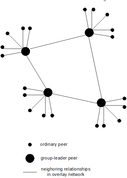
KaZaA: Motivation for Super-Nodes
- Query consolidation
- Many connected nodes may have only a few files
- Propagating query to a sub-node may take more time than for the super-node to answer itself
- Stability
- Super-node selection favors nodes with high up-time
- How long you’ve been on is a good predictor of how long you’ll be around in the future
9.10. Peer-to-Peer Networks: BitTorrent
![]()
BitTorrent history and motivation
- 2002: B. Cohen debuted BitTorrent
- Key motivation: popular content
- Popularity exhibits temporal locality (Flash Crowds)
- E.g., Slashdot effect, CNN Web site on 9/11, release of a new movie or game
- Focused on efficient fetching, not searching
- Distribute same file to many peers
- Single publisher, many downloaders
- Preventing free-loading
BitTorrent: Simultaneous Downloading
- Divide large file into many pieces
- Replicate different pieces on different peers
- A peer with a complete piece can trade with other peers
- Peer can (hopefully) assemble the entire file
- Allows simultaneous downloading
- Retrieving different parts of the file from different peers at the same time
BitTorrent Components
- Seed
- Peer with entire file
- Fragmented in pieces
- Leacher
- Peer with an incomplete copy of the file
- Torrent file
- Passive component
- Stores summaries of the pieces to allow peers to verify their integrity
- Tracker
- Allows peers to find each other
- Returns a list of random peers
BitTorrent:
Overall Architecture
1.

2.

3.

4.

5.

6.

7.
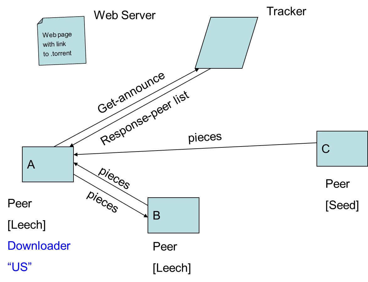
File
distribution: BitTorrent
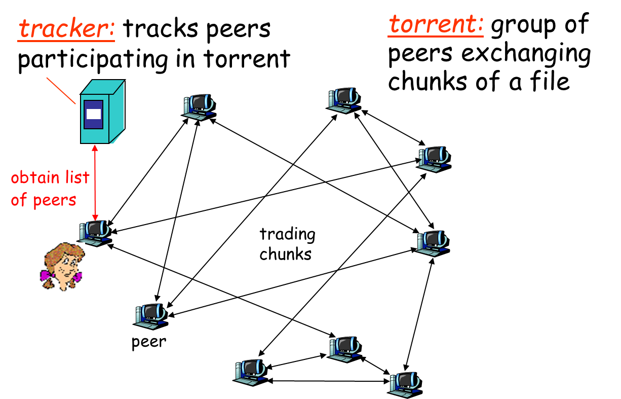
BitTorrent
(1)
- file divided into 256KB chunks.
- peer joining torrent:
- has no chunks, but will accumulate them over time
- registers with tracker to get list of peers, connects to subset of peers (“neighbors”)
- while downloading, peer uploads chunks to other peers.
- peers may come and go
- once peer has entire file, it may (selfishly) leave or (altruistically) remain
BitTorrent (2)
Pulling Chunks
- at any given time, different peers have different subsets of file chunks
- periodically, a peer (Alice) asks each neighbor for list of chunks that they have.
- Alice sends requests for her missing chunks
- rarest first
Sending Chunks: tit-for-tat
- Alice sends chunks to four neighbors currently sending her chunks at the highest rate
- re-evaluate top 4 every 10 secs
- every 30 secs: randomly select another peer, starts sending chunks
- newly chosen peer may join top 4
- “optimistically unchoke”
BitTorrent: Tit-for-tat
- Alice
“optimistically unchokes” Bob
- Alice
becomes one of Bob’s top-four providers; Bob reciprocates
- Bob
becomes one of Alice’s top-four providers

Free-Riding
Problem in P2P Networks
Vast majority of users are free-riders
- Most share no files and answer no queries
- Others limit # of connections or upload speed
A few “peers” essentially act as servers
- A few individuals contributing to the public good
- Making them hubs that basically act as a server
BitTorrent prevent free riding
- Allow the fastest peers to download from you
- Occasionally let some free loaders download
9.11. Overlay Networks
Overlay
Networks
1.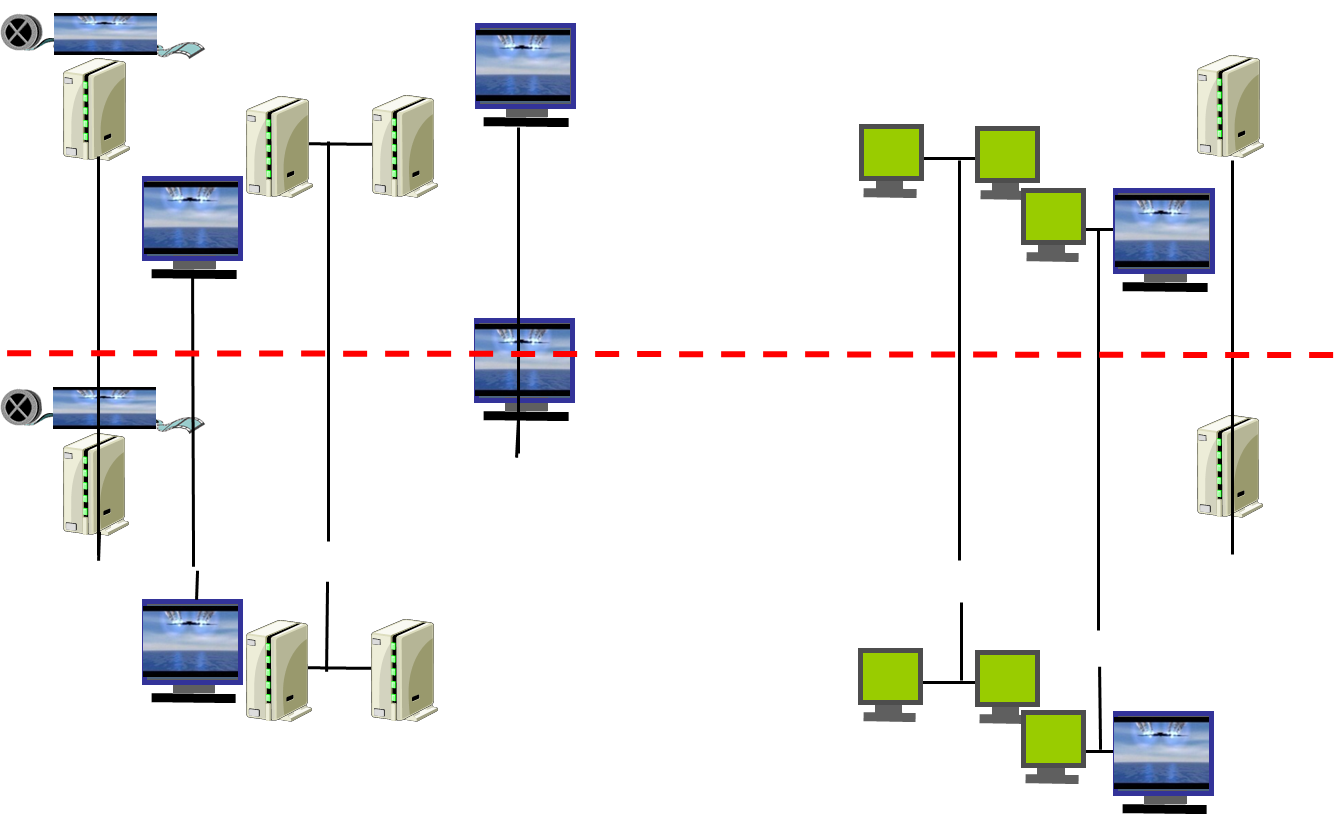
2.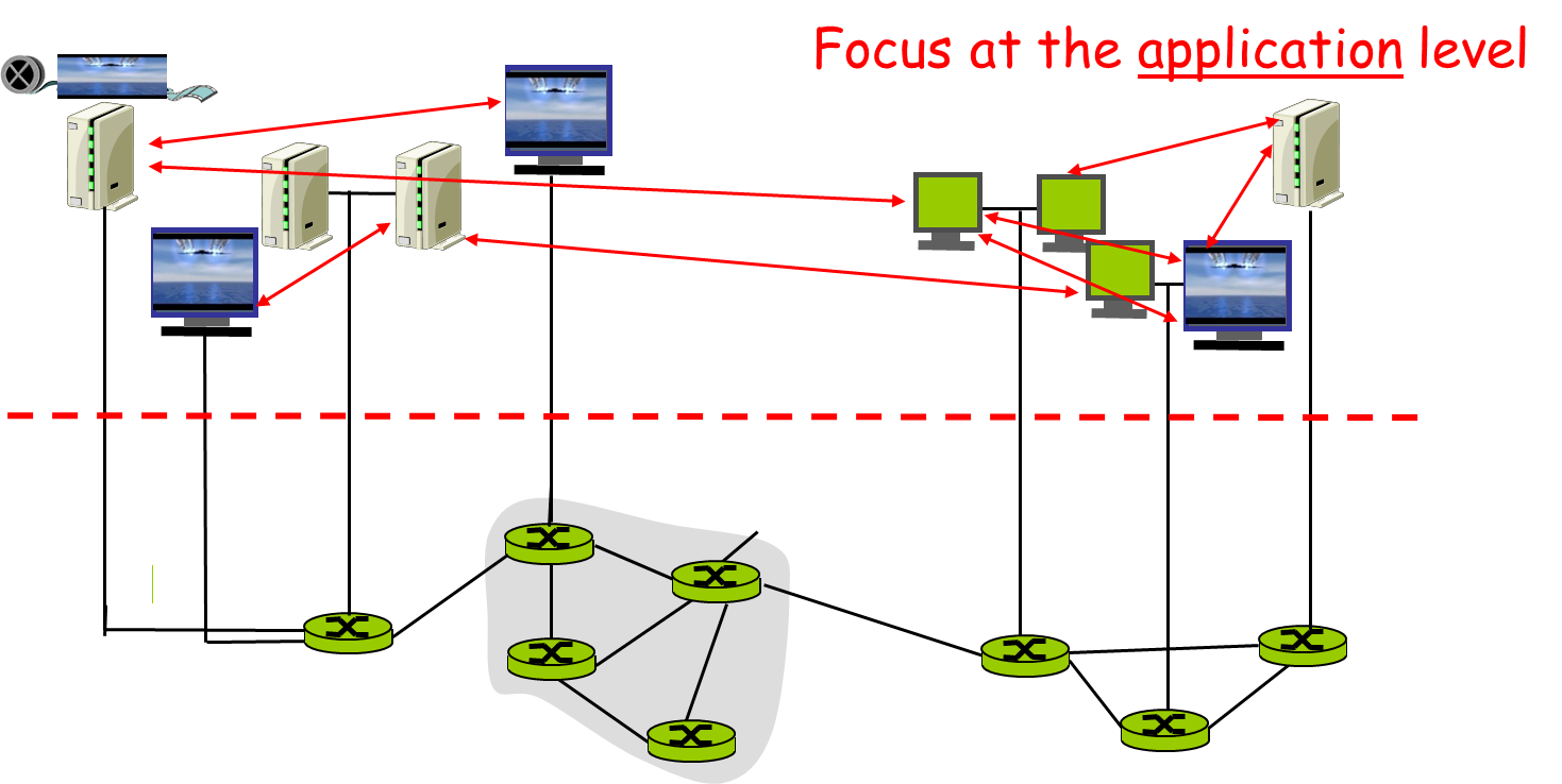
A logical network built on top of a physical network
- Overlay links are tunnels through the underlying network
Many logical networks may coexist at once
- Over the same underlying network
- And providing its own particular service
Nodes are often end hosts
- Acting as intermediate nodes that forward traffic
- Providing a service, such as access to files
Who controls the nodes providing service?
- The party providing the service (e.g., Akamai)
- Distributed collection of end users (e.g., peer-to-peer)
Overlays
P2P systems possess some degree of self-organization
- each node finds its peers and helps maintain the system structure
Two types of overlays connect most P2P systems
Unstructured
- No infrastructure set up for routing
- Random walks, flood search
Structured
- Small World Phenomenon: Kleinberg
- Set up enough structure to get fast routing
- We will see O(log n)
- For special tasks, can get O(1)
Overlays:
Unstructured
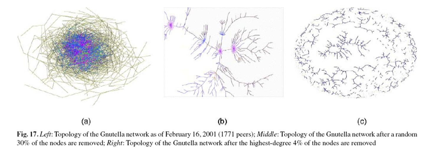
From Gribble
- a common unstructured overlay
- look at connectivity
- more structure than it seems at first
Gossip: state synchronization technique
- Instead of forced flooding, share state
- Do so infrequently with one neighbor at a time
- Original insight from epidemic theory
Convergence of state is reasonably fast
- with high probability for almost all nodes
- good probabilistic guarantees
Trivial to implement
- Saves bandwidth and energy consumption
Overlays:
Structured
Need to build up long distance pointers
- think of routing within levels of a namespace
- eg. namespace is 10 digit numbers base 4
- 0112032101
- then you can hop levels to find other nodes
This is the most common structure imposed
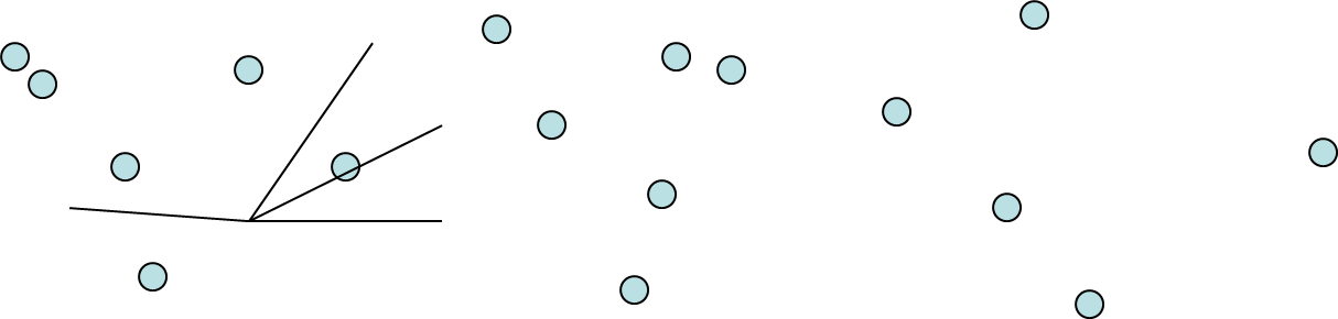
9.12. Distributed Hash Tables
One way to do this structured routing
- Assign each node each node an id from space
- eg. 128 bits: SHA-1 salted hash of IP address
- build up a ring: circular hashing
- assign nodes into this space
Value
- diversity of neighbors
- even coverage of space
- less chance of attack?
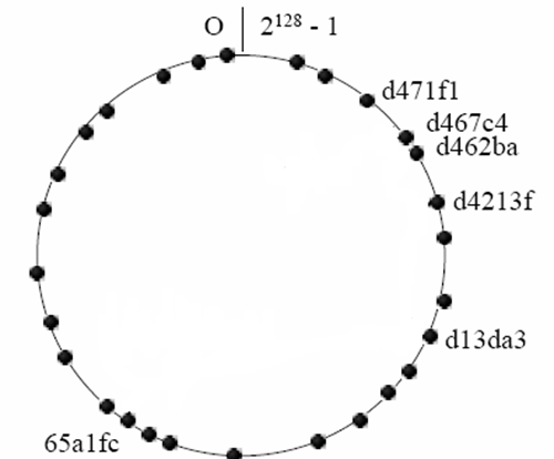
Why “hash tables”?
- Stored named objects by hash code
- Route the object to the nearest location in space
- key idea: nodes and objects share id space
How do you find an object without its name?
- Close names don’t help because of hashing
Cost of churn?
- In most P2P apps, many joins and leaves
Dangers
- Sybil attacks: one node becomes many
- id attacks: can place your node wherever
- Solutions hard to come by
- crytpo puzzles / money for IDs?
- Certification of routing and storage?
Many routing frameworks in this spirit
- Very popular in late 90s early 00s
- Pastry, Tapestry, CAN, Chord, Kademlia
9.13. Applications of DHTs
Almost anything that involves routing
- illegal file sharing: obvious application
- backup/storage
- filesystems
- P2P DNS
Good properties
- O(log N) hops to find an id (but how good is this?)
- Non-fate-sharing id neighbors
- Random distribution of objects to nodes
9.14. Conclusions
Peer-to-peer networks
- Nodes are end hosts
- Primarily for file sharing, and recently telephony
- Centralized directory (Napster), query flooding (Gnutella), super-nodes (KaZaA), and distributed downloading and anti-free-loading (BitTorrent)
- Tunnels between host computers
- Hosts implement new protocols and services
- Effective way to build networks on top of the Internet
Great example of how change can happen so quickly in application-level protocols